Shunt resistance type current sensor

a current sensor and resistance type technology, applied in the direction of instruments, base element modifications, measurement devices, etc., can solve the problems of failure to meet the requirements of the application, and etc., to achieve the effect of easy deformation, reduced heat dissipation of each connection terminal, and reduced difficulty in soldering work to the circuit board

Inactive Publication Date: 2016-04-21
YAZAKI CORP
View PDF3 Cites 8 Cited by
  • Summary
  • Abstract
  • Description
  • Claims
  • Application Information

AI Technical Summary

Benefits of technology

[0025]According to the embodiments of the invention, in the predetermined range from the tip side of the connection terminal, the area reduced in its plate thickness than that of the bus bar is set, and then the tip side of the each connection terminal penetrates the circuit board. Thus, as the circuit board side does not require large through holes, the circuit board is not required to have a large space. Further, as heat dissipation of the each connection terminal can be made small, such a problem that a soldering work to the circuit board is difficult can be suppressed. Furthermore, as the connection terminal is easily deformed, a stress can be relieved even if a difference in thermal expansion is generated between the bus bar and the circuit board. Thus, degradation in reliability such as generation of cracks in soldered parts can be suppressed. In this manner, the connection between the connection terminal and the circuit board can be performed satisfactorily while integrally forming the connection terminals with the bus bar.

Problems solved by technology

As a result, following problems may be raised in a case of penetrating the connection terminals through a circuit board.
Firstly, as large through holes are required on the circuit board side, the circuit board is required to have a sufficient space corresponding to these through holes.
Secondly, as a degree of temperature drop due to heat dissipation of the connection terminals is large, a soldering work to the circuit board is difficult.
Thirdly, if a difference in thermal expansion is generated between the bus bar and the circuit board, as the connection terminals are unlikely deformed, a stress cannot be relieved, therefore, reliability may degrade due to generation of cracks in soldered parts.

Method used


Image

  • Shunt resistance type current sensor
  • Shunt resistance type current sensor
  • Shunt resistance type current sensor

Examples


Embodiment Construction

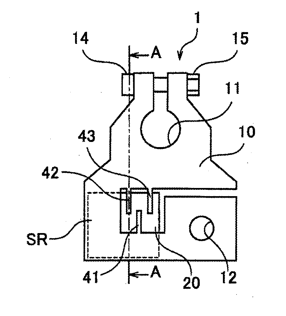
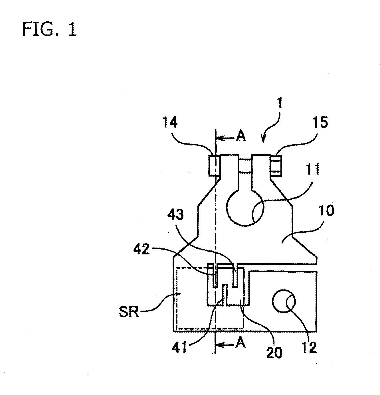
[0036]FIG. 1 is a top view schematically showing a shunt resistance type current sensor 1 according to an embodiment. FIG. 2 is a bottom view schematically showing the shunt resistance type current sensor 1 according to the embodiment. FIG. 3 is a side view schematically showing the shunt resistance type current sensor 1 shown in FIG. 1 and shows a state of the shunt resistance type current sensor 1 shown in FIG. 1 seen from a lower side of the sheet. The shunt resistance type current sensor 1 is used as a battery terminal and mainly configured of a bus bar 10 and a circuit board 20.

[0037]The bus bar 10 is a conductive member of a substantially flat plate shape and constituted of, for example, copper-manganese alloy, copper-nickel-alloy or the like. A part of the bus bar 10 can be acted as a shunt resistance part SR. The bus bar is configured in a manner that current to be measured flows in the shunt resistance part SR when current flows in the bus bar 10. The bus bar 10 is formed t...


PUM


Abstract

A shunt resistance type current sensor includes a bus bar, a circuit board disposed to oppose the bus bar, a shunt resistance part in the bus bar, connection terminals which electrically connect the bus bar and the circuit board, and a voltage detector which is mounted on the circuit board and detects a voltage applied to the bus bar to detect a magnitude of current to be measured flowing through the bus bar. The connection terminal is formed integrally with the bus bar as an extending piece extended from an edge part of the bus bar, an area of the connection terminal reduced in its plate thickness than that of the bus bar is set in a range from a tip side thereof, and the tip side of the connection terminal penetrates the circuit board and connects with the circuit board.

Description

CROSS REFERENCE TO RELATED APPLICATIONS[0001]This application is a continuation of PCT application No. PCT / JP2014 / 067089, which was filed on Jun. 26, 2014 based on Japanese Patent Application (No. 2013-149283) filed on Jul. 18, 2013, the contents of which are incorporated herein by reference.BACKGROUND OF THE INVENTION[0002]1. Field of the Invention[0003]One or more embodiments of the present invention relate to a shunt resistance type current sensor.[0004]2. Description of the Related Art[0005]There has been proposed a shunt resistance type current sensor in which current to be measured flows into a shunt resistor having a known resistance value in order to detect a pulse current, a large AC current or the like, and a voltage drop generated across the shunt resistor is detected, thereby measuring a magnitude of the current to be measured. For example, in a vehicle such as an automobile, a metal piece called a bus bar is sometimes used for power distribution, and a part of the bus b...

Claims


Application Information

Patent Timeline
Patent Type & Authority Applications(United States)
IPC IPC(8): G01R1/20G01R19/00G01R31/36
CPCG01R1/203G01R19/0092G01R31/3696G01R31/364H01C13/00
Inventor SATO, TAKASHIUMEHARA, SHIN
Owner YAZAKI CORP
Why Eureka
Try Eureka