Electric steering device

a technology of steering device and steering wheel, which is applied in the direction of steering initiation, vessel parts, instruments, etc., can solve the problem that the correction of the running direction cannot be carried out simply, and achieve the effect of facilitating the easy correction of the predetermined steering level by the turning motor

Inactive Publication Date: 2012-11-29
HONDA MOTOR CO LTD
View PDF4 Cites 38 Cited by
  • Summary
  • Abstract
  • Description
  • Claims
  • Application Information

AI Technical Summary

Benefits of technology

[0017]Hence, when the steering angle of the steering wheel to the right or left exceeds the predetermined first threshold, the right or left operation unit that is easy for the driver to operate can generate and output the predetermined additional current value waveform in accordance with the driving condition information on a vehicle, which facilitates the correction of the predetermined level of steering by the turning motor.
[0032]According to the eleventh aspect of the present invention, the control unit causes the turning motor to drive the turning mechanism in accordance with a steering input to the steering wheel, and controls the turning motor by generating and outputting the predetermined additional current value waveform depending on the driving condition information on the vehicle in accordance with an operation to the operation unit provided at the steering wheel. This makes it possible for the turning motor to easily correct the predetermined level of steering. That is, the correction of the predetermined level of the steering by the turning motor is facilitated in a steer-by-wire type electric steering device.

Problems solved by technology

For example, provided that a four-wheel vehicle is running substantially straight, when a driver periodically performs steering operation for correction of the vehicle's running direction substantially constantly in the right or left direction in accordance with a change in the road condition, if such a correction steering operation is performed by the driver through the rotational angle of the grip or through the operation of the switch, it is necessary to adjust the rotational angle of the grip and the operation time of the switch, and thus correction of the running direction cannot be simply carried out.

Method used


Image

  • Electric steering device
  • Electric steering device
  • Electric steering device

Examples


first embodiment

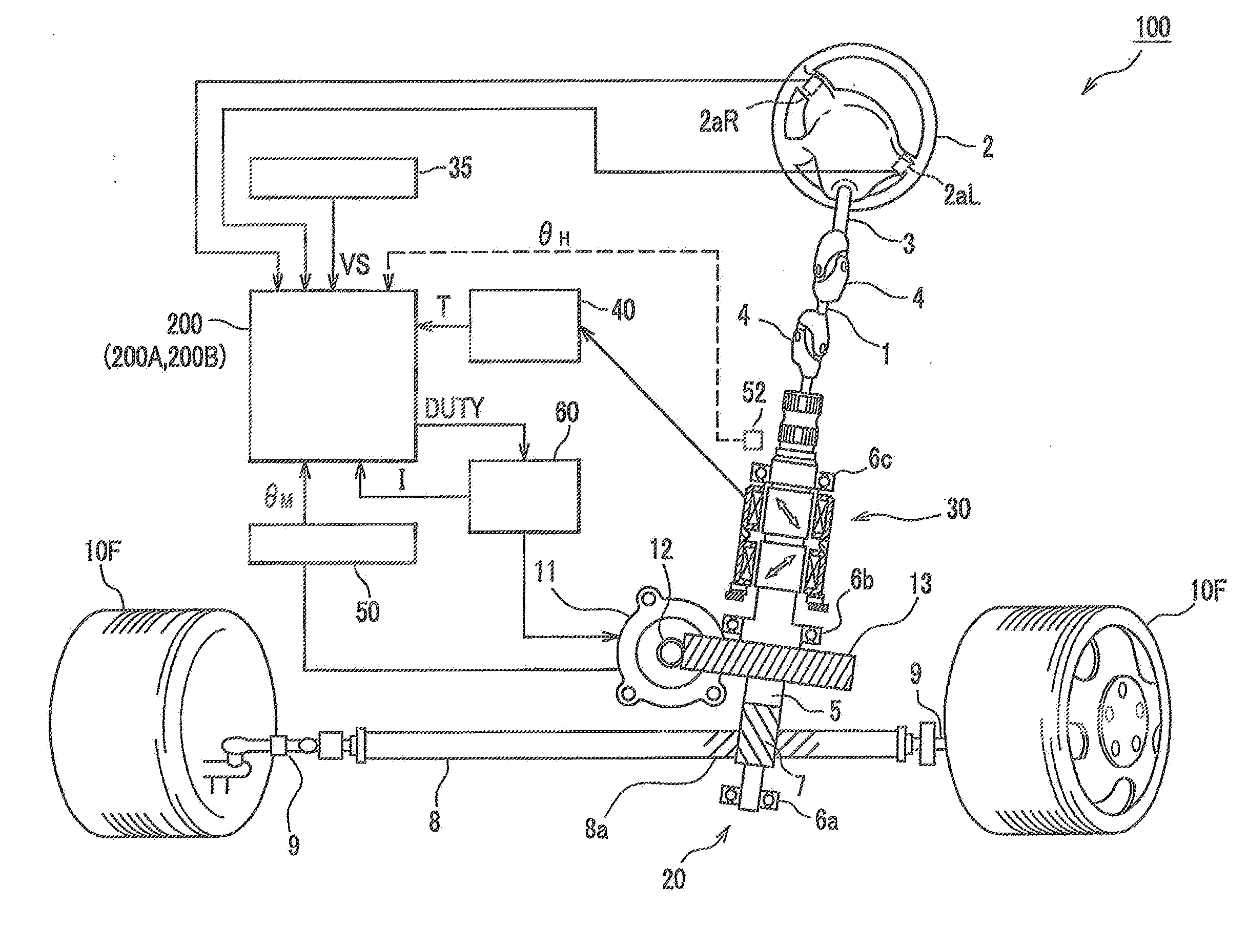
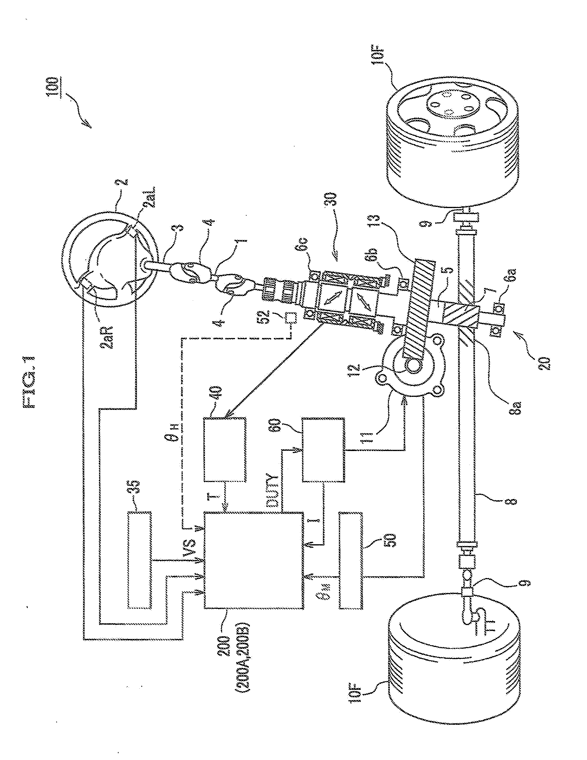
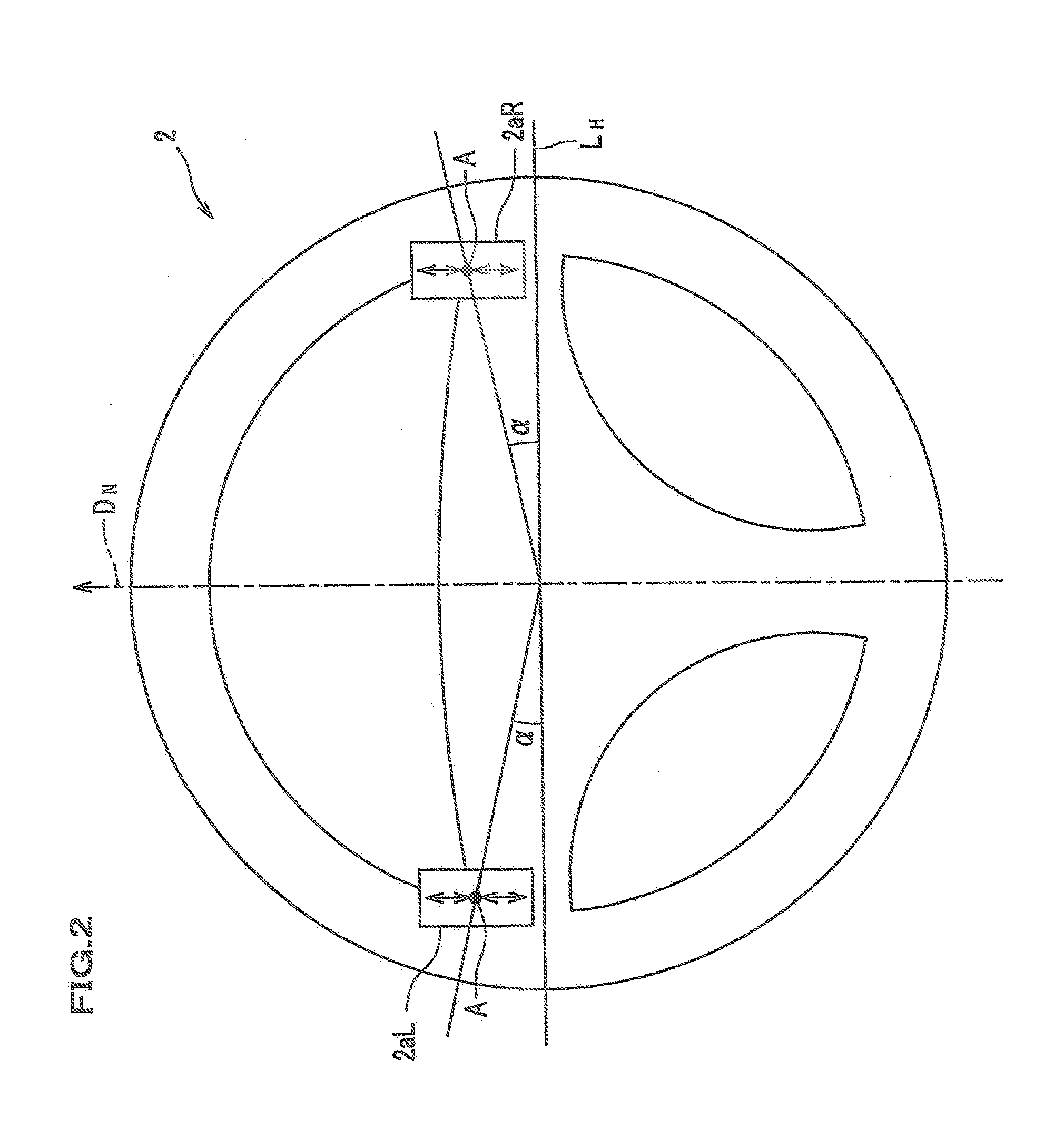
[0061]An electric power steering device according to a first embodiment of the present invention will be explained with reference to FIGS. 1 to 3. FIG. 1 is a configuration diagram of an electric power steering device according to this embodiment. FIG. 2 is an explanatory diagram showing an operation switch provided on a steering wheel shown in FIG. 1. FIG. 3 is a functional block configuration diagram of a control device according to the first embodiment.

[0062]

[0063]As shown in FIG. 1, an electric power steering device (an electric steering device) 100 includes a main steering shaft 3 provided with a steering wheel 2, a shaft 1, and a pinion shaft 5 which are coupled together by two universal joints 4, 4. Moreover, a pinion gear 7 provided at the lower end of the pinion shaft 5 is meshed with rack teeth 8a of a rack shaft 8 that can reciprocate in the width direction of a vehicle, and unillustrated knuckle arms of front wheels (turning wheels) 10F, 10F that are right and left turni...

first modified example of first embodiment

[0215]According to the first embodiment, as shown in FIGS. 5A and 5B, when the output waveform computing unit 297A generates the current waveform of the additional current value IAd, the output waveform monitoring unit 299 calculates the threshold time tth that is a timing at which the output of the output current of the additional current value IAd is started, reaches the wave height (H0×K) / e, starts falling and such a wave height becomes lower than the value of (H0×K) / e, and the threshold time tth is input into the switch operation determining unit 290A. However, the present invention is not limited to such a configuration.

[0216]The output waveform monitoring unit 299 may monitor in the step S13 in FIG. 12 the additional current value IAd for each time step and output from the additional current-output control unit 298 indicated by an arrow of a dashed line based on the current waveform of the additional current value IAd generated by the output waveform computing unit 297A, set I...

second modified example of first embodiment

[0217]According to the first embodiment, in the steps S03 to S10 in FIG. 11, the explanation was given based on the presumption to the above-explained first method explained in the paragraph “0068” that is a control method of outputting / not outputting the additional current value IAd on the basis of the combination of the function of the operation switch validity determining unit 295 which determines that the operation to the operation switches 2aL and 2aR is valid, and the function of the switch operation determining unit 290A.

[0218]However, the present invention is not limited to such a method, and the second method explained in the paragraphs “0069” and “0070” may be applied. In this case, when the determination result in the step S03 is NO, the operation switch validity determining unit 295 further determines whether or not the steering angle θH is, for example, within 90 degrees to the right and left. When the steering angle is within 90 degrees to the right and left, in the ca...


PUM


Abstract

An electric steering device is provided which enables a stable steering correction operation expected by a driver. An electric power steering device having a motor, which is controlled by a control device based on steering torque and generates steering assist force, further includes operation switches which are provided at a steering wheel and which output electric signals based on an operation given by a driver, and an additional current computing unit that calculates and outputs an additional current value waveform for adding a current for driving the motor in accordance with the electric signals from the operation switches. The additional current computing unit generates and outputs the current waveform of a predetermined additional current value in accordance with the driving condition information on a vehicle in response to an operation to the operation switch regardless of the time length of the ON state of the operation switches.

Description

CROSS REFERENCE TO RELATED APPLICATION[0001]This application claims the priority of Japanese Applications Nos. 2011-114302, filed on May 23, 2011, and 2011-115258, filed on May 23, 2011, the entire specifications, claims and drawings of which are incorporated herewith by reference.BACKGROUND OF THE INVENTION[0002]1. Field of the Invention[0003]The present invention relates to an electric steering device which drives a steering mechanism thorough a motor (a steering motor) or which applies steering assist force to the steering mechanism.[0004]2. Description of the Related Art[0005]An electric power steering device causes a motor to generate steering assist force in accordance with the level of steering wheel torque, transmits the steering assist force to a steering system, thereby reducing the steering effort by a driver. JP 2002-59855 A (see FIG. 2) and JP 2000-177615 A (see FIG. 2) disclose technologies of compensating a base current (assist torque) defined based on steering wheel ...

Claims


Application Information

Patent Timeline
Patent Type & Authority Applications(United States)
IPC IPC(8): B62D6/00B62D6/02B62D5/04
CPCB62D1/02B62D1/046B62D5/0463H02P21/06B62D6/007B62D6/02H02P21/0089B62D6/00
Inventor TAMURA, NORIFUMITADA, YOSHINOBUMATSUMOTO, YOSHIYUKITOKUNAGA, HIROYUKI
Owner HONDA MOTOR CO LTD
Why Eureka
Try Eureka