

Low elongation structures for hot gas filtration
a technology of low elongation and hot gas, applied in the direction of filtration separation, separation process, paper/cardboard containers, etc., can solve the problems of subsequent media dimensional change and mechanical stress, and achieve the effect of maintaining the stability of the filter media and minimizing the elongation properties
Inactive Publication Date: 2012-12-06
EI DU PONT DE NEMOURS & CO
View PDF3 Cites 9 Cited by
- Summary
- Abstract
- Description
- Claims
- Application Information
AI Technical Summary
Problems solved by technology
This leads to mechanical stress and subsequent media dimensional change such as elongation.
Method used
View moreImage
Smart ImageViewing Examples

Examples
examples
[0043]A) PPS Spunlaced Structures without-, with Metal-, Glass- and PPS Scrims
example 1
Spunlaced Filtration Structure of PPS Fibers with Metal Mesh Scrim
[0045]A spunlaced filtration structure was made following a procedure similar to that described in Example 1 except that prior tohydro lacing a 420 gsm heavy metal mesh scrim was inserted. The filter structure made had a basis weight of 781 grams per square meter.
example 2
Spunlaced Filtration Structure of PPS Fibers with Laid Glass Scrim
[0046]A spunlaced filtration structure was made following the procedure described in Example 1 except that prior to hydro lacing a 68 gsm laid glass scrim was inserted. The filter structure made had a basis weight of 417 grams per square meter
Login to View More PUM
| Property | Measurement | Unit |
|---|---|---|
| heat resistance | aaaaa | aaaaa |
| width | aaaaa | aaaaa |
| elongation | aaaaa | aaaaa |
Abstract
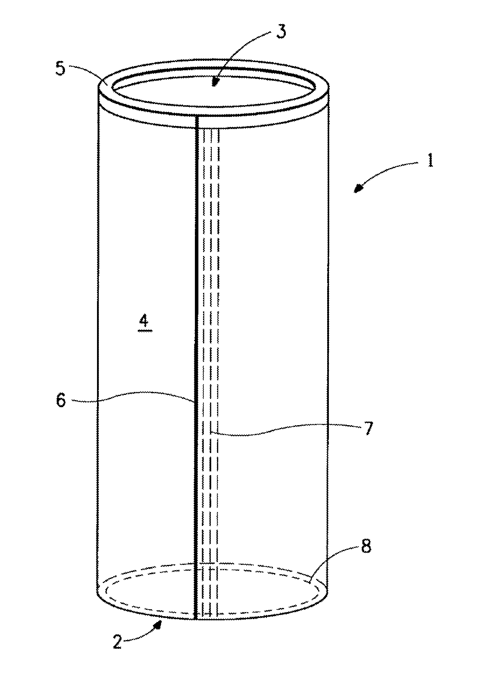
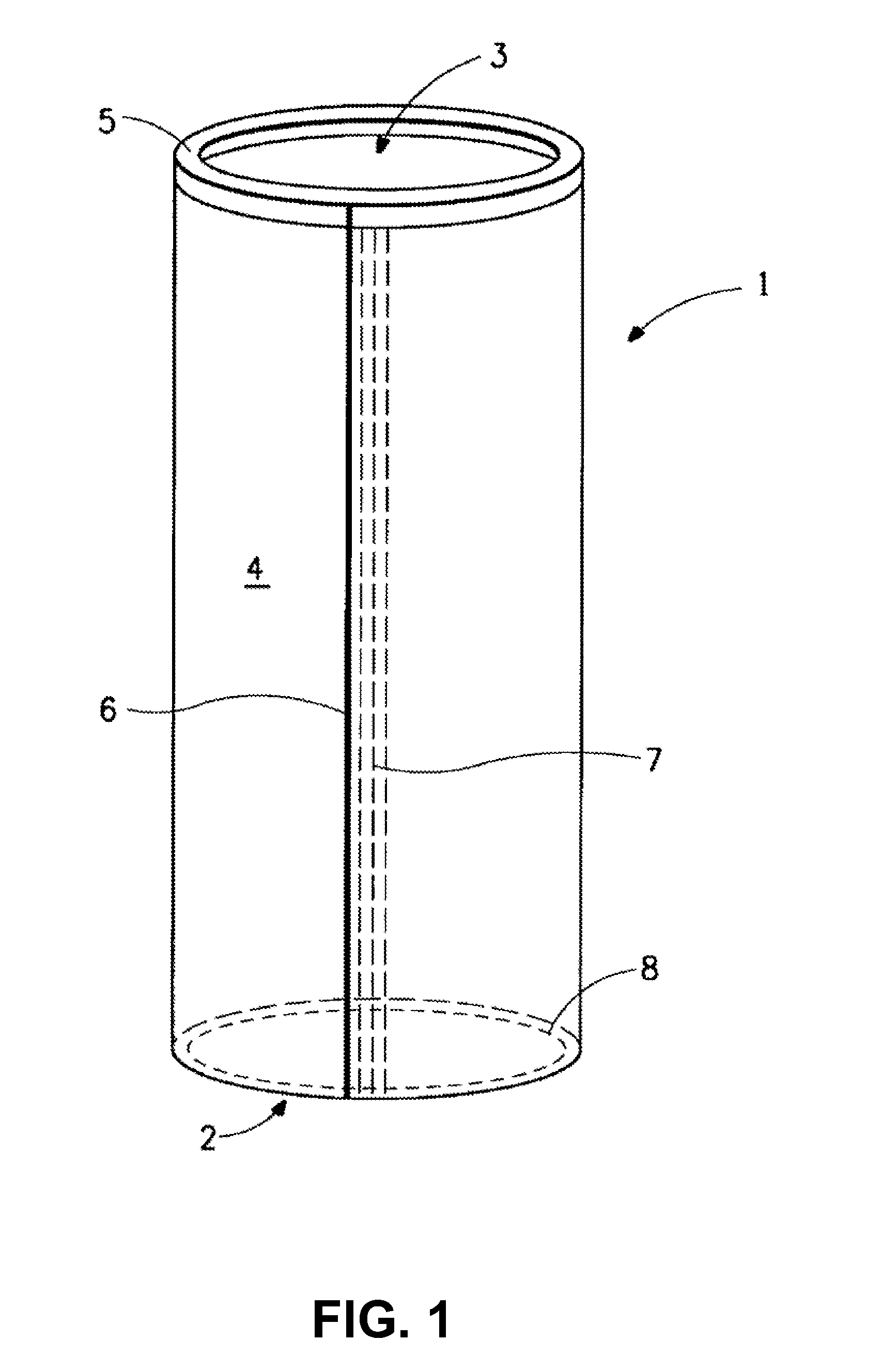
Structures containing a fiber mat inserted into a high modulus scrim of minimum basis weight 35 gsm. The structures have reduced tensile elongation at 50 N per 5 cm fabric strip in MD under ISO 9073-3 standard norm. The structure has a basis weight of at least 9 ounces per square yard (305 grams per square meter). The structure also has heat resistance of at least 150° to 190° C., preferably over 200 up to 260° C. to for service under typical hot flue gas filtration conditions. Filter bags made from these structures provide a controlled dimensional stability over their entire filter life time. In addition such stable structures are suitable for lamination with fragile membranes especially e-PTFE membranes where minimum amount of mechanical damage to the membrane occurs.
Description
BACKGROUND OF THE INVENTION[0001]The use of fabric filters has grown significantly as environmental standards for particulate emissions have become more stringent. Fabric filters are used because they are highly efficient, easily operated and in many cases the least expensive method of control of such emissions. Filter bag fabric is of extreme importance since one fabric may function much better than another fabric in the same environment. During the filtration process, the filtering media stops and collect particles on its surface or in depth. All along its work life, and according to filtering equipment design, media sustains its own weight combined with collected particles mass. This leads to mechanical stress and subsequent media dimensional change such as elongation. New filter fabric constructions of improved filtering capacity over its entire service life is a desirable goal. The present invention is for a filter fabric and a filter with low elongation, capable of maintaining...
Claims
Login to View More Application Information
Patent Timeline
 Patent Type & AuthorityApplications(United States)
IPC IPC(8): B01D39/14B32B37/00B01D46/02D04H1/4209D04H1/4282D04H1/4326D04H1/46
CPCB32B3/04Y10T156/10B32B5/06B32B5/26B32B2262/02B32B2262/0269B32B2307/306B32B2307/54B32B2459/00D04H1/4209D04H1/4282D04H1/4326D04H1/46D04H13/00B32B5/028
InventorWYSS, KURT HANSALBERTONE, YANNICK
OwnerEI DU PONT DE NEMOURS & CO