

Document reading apparatus
- Summary
- Abstract
- Description
- Claims
- Application Information
AI Technical Summary
Benefits of technology
Problems solved by technology
Method used
Image

Examples
Embodiment Construction
[0018]Various exemplary embodiments, features, and aspects of the invention will be described in detail below with reference to the drawings.
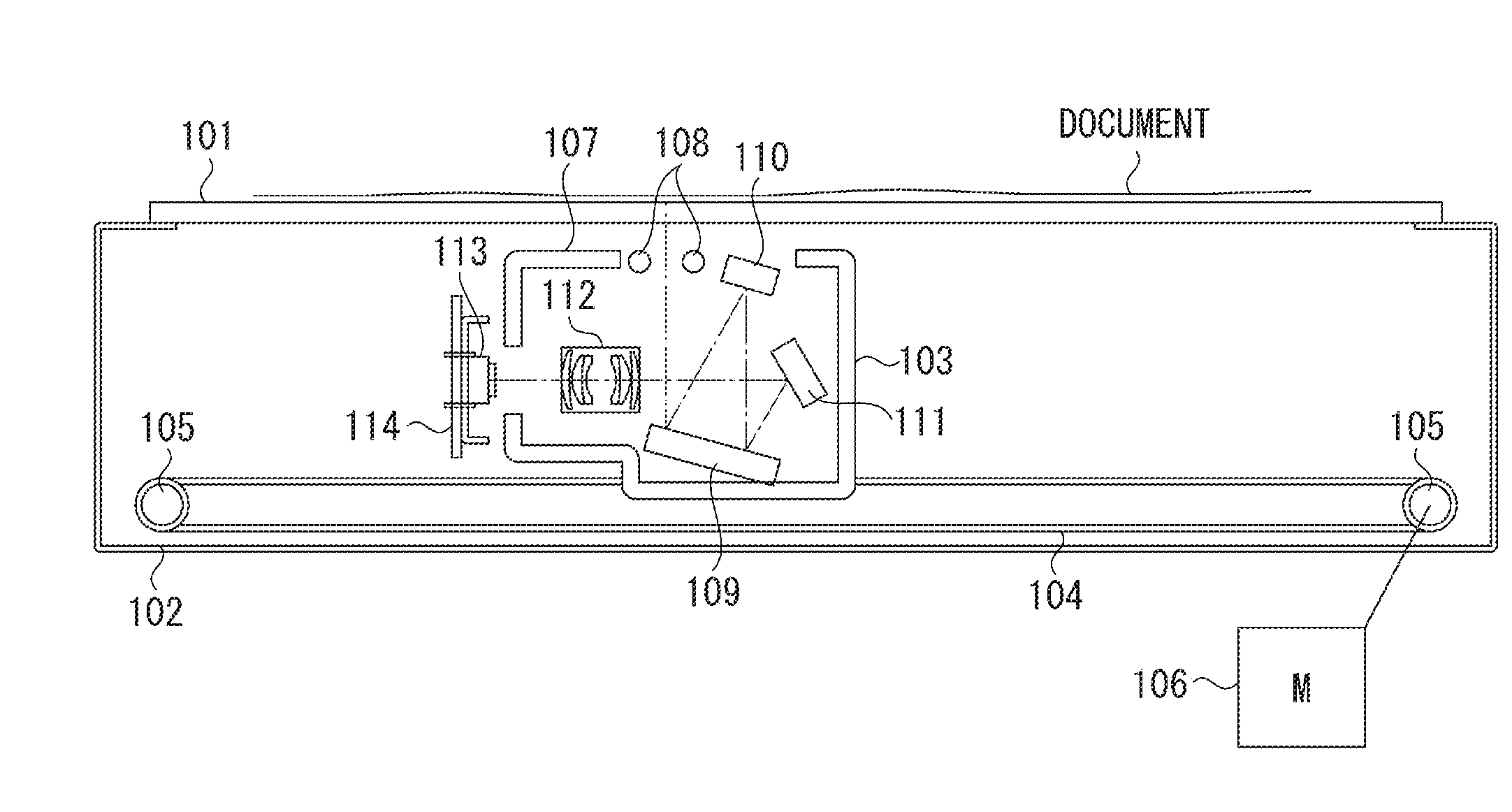
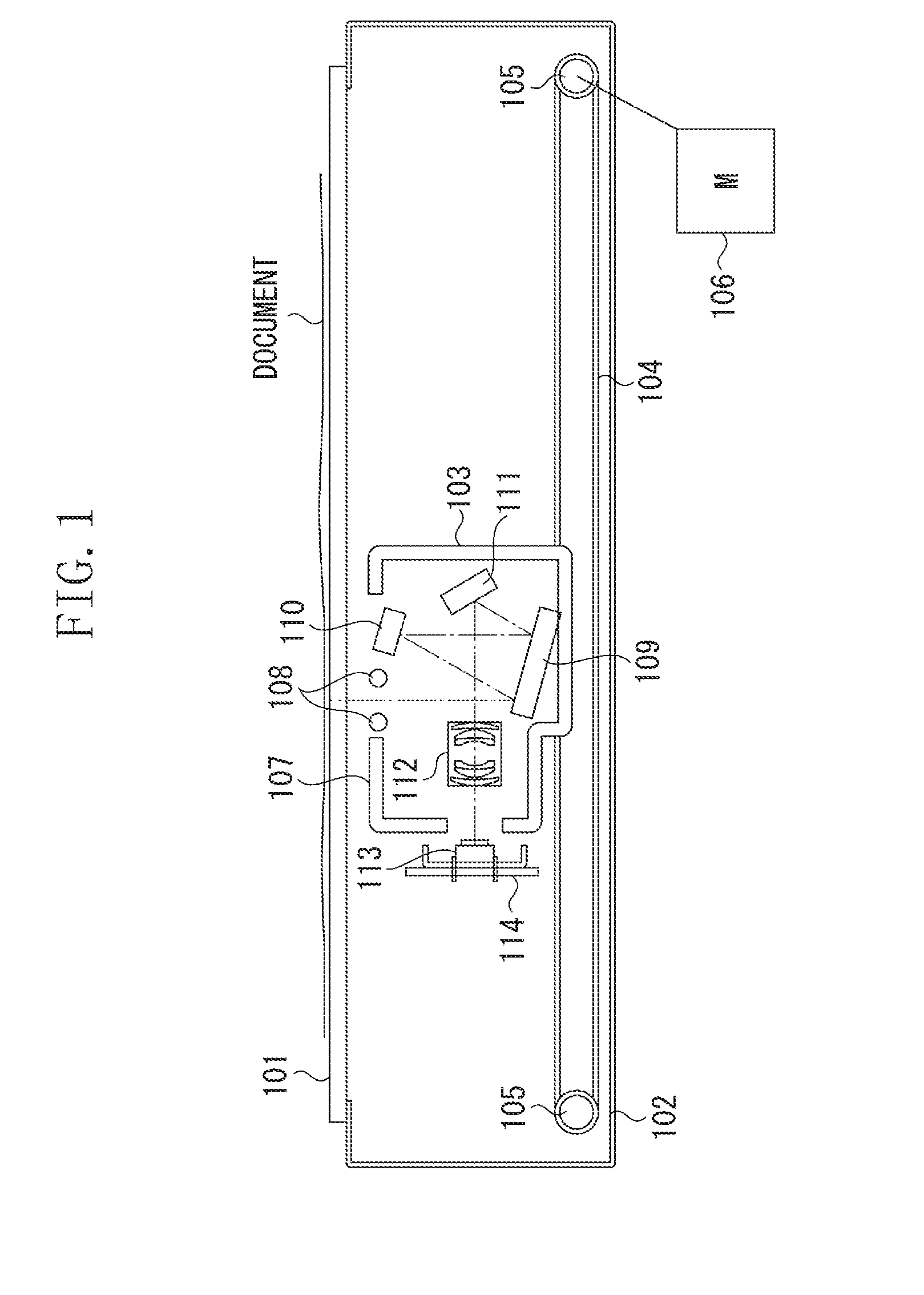
[0019]A first exemplary embodiment will be described. FIG. 1 illustrates an outline of a configuration of an image reading apparatus according to the first exemplary embodiment.
[0020]A document is placed on a platen glass 101. A frame member 102 supports the platen glass 101. A scanning unit 103 moves, according to movement of a belt 104, between two pulleys 105 that drive the belt 104 to scan the document placed on the platen glass 101. A motor 106 rotationally drives one of the pulleys 105.
[0021]The scanning unit 103 includes a carriage frame member 107, a light source 108 that illuminates the document, reflection mirrors 109, 110, and 111 that guide a light diffused from the document, a lens 112 that causes the light to form a focused-image, a CCD 113 serving as a reading element that photoelectrically converts and reads out the image-formed...
PUM
 Abstract
Description
Claims
Application Information