Synchronous permanent magnet machine

a permanent magnet machine and synchronous technology, applied in the direction of dynamo-electric machines, synchronous machines with stationary armatures and rotating magnets, electrical apparatus, etc., can solve the problems of weaker low energy-product magnets, and poor demagnetization performance, and achieve weak low energy-product magnets, good demagnetization performance, and good demagnetization performan

Active Publication Date: 2012-12-13
SIEMENS GAMESA RENEWABLE ENERGY AS
View PDF5 Cites 14 Cited by
  • Summary
  • Abstract
  • Description
  • Claims
  • Application Information

AI Technical Summary

Problems solved by technology

This is disadvantageous as it can give rise to appreciable cogging torque and torque ripple on load when the arrangement is in use in a synchronous permanent magnet machine.
The arrangement also has the disadvantage that the weaker low energy-product magnets 3a, 3b, 3c, 3d are relatively poor at withstanding demagnetization when the arrangement is in use in a synchronous permanent magnet machine.

Method used


Image

  • Synchronous permanent magnet machine
  • Synchronous permanent magnet machine
  • Synchronous permanent magnet machine

Examples


Embodiment Construction

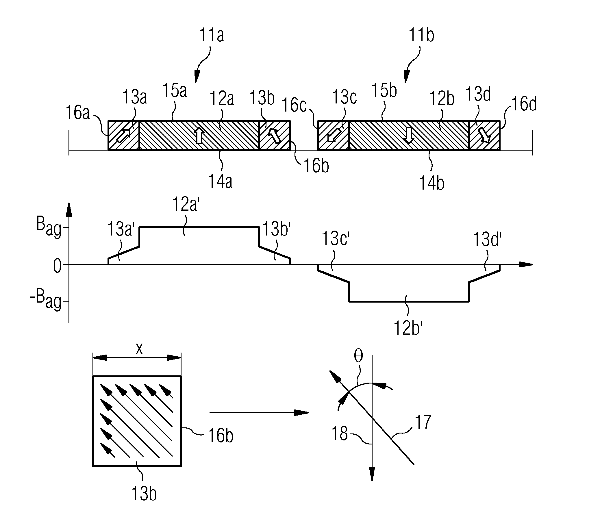
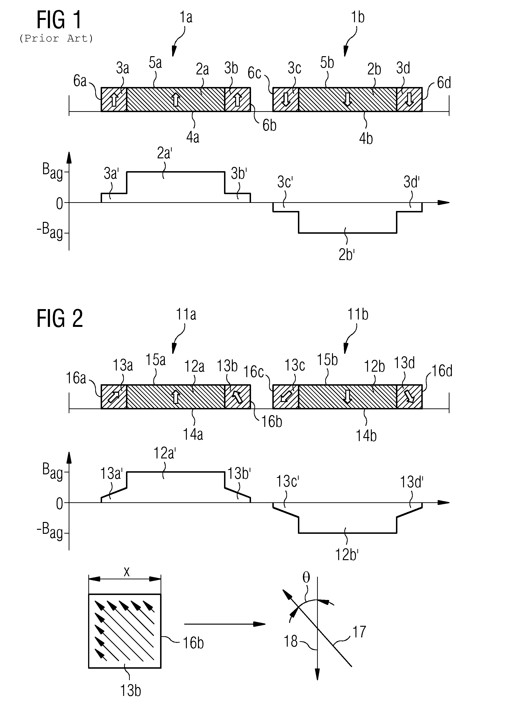
[0014]FIG. 2 shows a pair of adjacent permanent magnet poles 11a, 11b, each pole comprising a central, main, high energy-product magnet 12a, 12b, and, to either side of the magnet 12a, 12b, side, subsidiary, low energy-product magnets 13a, 13b, 13c, 13d. Each pole 11a, 11b has a base 14a, 14b, top face 15a, 15b, and sides 16a, 16b, 16c, 16d. The arrows on the magnets 12a, 12b, 13a, 13b, 13c, 13d represent the direction of magnetization of the magnets. The high energy-product magnet 12a of pole 11a has a direction of magnetization directed perpendicularly away from the base 14a of the pole. The low energy-product magnets 13a, 13b of pole 11a have directions of magnetization directed away from the base 14a of the pole and towards the high energy-product magnet 12a of the pole. The high energy-product magnet 12b of adjacent pole 11b has a direction of magnetization directed perpendicularly towards the base 14b of the pole. The low energy-product magnets 13c, 13d of pole 11b have direct...


PUM


Abstract

A synchronous permanent magnet machine includes a permanent magnet arrangement for producing a magnetic field having a flux density distribution that is approximately sinusoidal. The permanent magnet arrangement includes a permanent magnet pole with both low and high energy-product magnets. The permanent magnet pole includes a low energy-product magnet and a high energy-product magnet which have different directions of magnetization, or a disposition of low / high energy-product magnets within the permanent magnet pole is asymmetric with respect to the central region of the permanent magnet pole.

Description

CROSS REFERENCE TO RELATED APPLICATIONS[0001]This application claims priority of European Patent Office Application No. 11162813.7 EP filed Apr. 18, 2011. All of the applications are incorporated by reference herein in their entirety.FIELD OF INVENTION[0002]A synchronous permanent magnet machine is provided. More particularly, a synchronous permanent magnet machine is provided, which includes a permanent magnet arrangement for producing a magnetic field having a flux density distribution that is approximately sinusoidal, the permanent magnet arrangement including a permanent magnet pole having a base, top face, sides, and a central region midway between the sides and extending between the base and top face, the permanent magnet pole being made up of both low and high energy-product magnets. An example of a low energy-product magnet is ferrite. Examples of high energy-product magnets are Neodymium-Iron-Boron and Samarium-Cobalt.BACKGROUND OF INVENTION[0003]One such permanent magnet a...

Claims


Application Information

Patent Timeline
Patent Type & Authority Applications(United States)
IPC IPC(8): H02K21/12
CPCH02K1/27H02K29/03H02K21/12
Inventor CHEN, JIN-TAOZHU, ZI-QIANG
Owner SIEMENS GAMESA RENEWABLE ENERGY AS
Why Eureka
Try Eureka