
Display device
a technology of a display device and a liquid crystal layer, which is applied in the field of display devices, can solve the problems of reducing lens performance and lowering display quality, and achieve the effects of reducing light scattering, reducing display quality, and great difference in refractive index between a spacer bead and the liquid crystal layer
- Summary
- Abstract
- Description
- Claims
- Application Information
AI Technical Summary
Benefits of technology
Problems solved by technology
Method used
Image

Examples
first embodiment
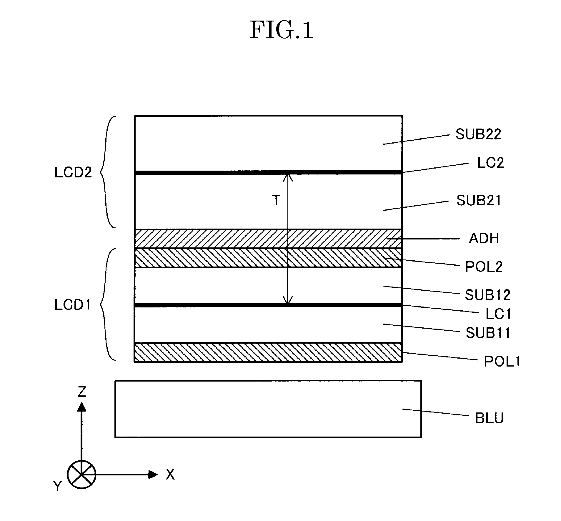
[0041]FIG. 1 is a cross-sectional diagram for illustrating the entire structure of the liquid crystal display device, which is the display device according to the first embodiment of the present invention. In the following, the entire structure of the display device according to the first embodiment is described in reference to FIG. 1. Though a case where a non-luminous type first liquid crystal display panel LCD1 is used as a display panel for displaying an image is described in the following, the display panel for displaying an image may be of another non-luminous type display panel or have a structure where a self-luminous type display panel, such as an organic EL display panel or a plasma display panel, is used.
[0042]The liquid crystal display device according to the first embodiment is formed of a first liquid crystal display panel LCD1, which is a liquid crystal display panel for displaying an image, and a second liquid crystal display panel LCD2 that functions as a lens (lent...
second embodiment
[0087]FIG. 13 is a cross-sectional diagram for schematically illustrating the structure of the second liquid crystal display panel in the display device according to the second embodiment of the present invention and corresponds to FIG. 8 of the first embodiment. Here, the structure of the display device according to the second embodiment is the same as that in the first embodiment, except for the structure of the second liquid crystal display panel LCD2. Accordingly, the structure of the second liquid crystal display panel LCD2 is described below in detail.
[0088]As shown in FIG. 13, the second liquid crystal display panel LCD2 in the second embodiment is formed using spacer beads SB, which are spherical spacers, as the spacers (spacer members). In the case where spacer beads SB are simply used, the display light is scattered by the spacer beads SB, which lowers the image quality in the same manner as in the second liquid crystal display panel LCD2 according to the prior art. Accord...
third embodiment
[0093]FIGS. 14 and 15 are diagrams for schematically illustrating the structure of the second liquid crystal display panel in the display device according to the third embodiment of the present invention. In particular, FIG. 14 is a plan diagram for schematically illustrating the structure of the first substrate SUB21 for forming the second liquid crystal display panel LCD2, and FIG. 15 is a plan diagram for schematically illustrating the structure of the second substrate SUB22 for forming the second liquid crystal display panel LCD2.
[0094]As is clear from FIGS. 14 and 15, the second liquid crystal display panel LCD2 in the third embodiment is formed such that post spacers PS1 and PS2 are respectively formed on the first substrate SUB21 and the second substrate SUB22, which are placed so as to face each other with a liquid crystal layer LC2 in between, on the liquid crystal side. At this time, the post spacers PS1 and PS2 in the third embodiment are formed as plates where the shape ...
PUM
| Property | Measurement | Unit |
|---|---|---|
| angle | aaaaa | aaaaa |
| angle | aaaaa | aaaaa |
| rubbing angle | aaaaa | aaaaa |
Abstract
Description
Claims
Application Information