Sealing Device For An Immersible Pump

Active Publication Date: 2012-12-13
HAYWARD IND INC
View PDF12 Cites 2 Cited by
  • Summary
  • Abstract
  • Description
  • Claims
  • Application Information

AI Technical Summary

Benefits of technology

[0004]In some embodiments, an apparatus is provided that includes a shaft for communicating with a motor, wherein the shaft includes a first region having a first diameter, a second region having a second diameter that is less than (e.g., skinnier than) the first diameter, and a tapering region between the two regions. The apparatus may also include a sleeve having a bore configured to receive the shaft, and a sealing device. The sealing device can include a receiving area configured so that the tapering region of the shaft is positionable at least partially therein to form a seal therewith, and can further include an abutment that is configured to form a seal with the sleeve and that is responsive to a force directed from the sleeve to enhance the seal with the tapering region. The sealing device can have a circumferential outer wall positionable proximal the sleeve. The circumferential outer wall is preferably provided as a cylindrical wall, though it can be provided as a pseudo-cylindrical wall (e.g., rectilinear, octagonal, etc.) with geometry complementary to the shaft and sleeve. In some embodiments, the abutment may be formed by an annular ring, positioned between the re

Problems solved by technology

Often, the fluid being pumped contains corrosive liquid chemicals.
However, a small space remains between the shaft and the sleeve where fluid may enter.

Method used


Image

  • Sealing Device For An Immersible Pump
  • Sealing Device For An Immersible Pump
  • Sealing Device For An Immersible Pump

Examples


Embodiment Construction

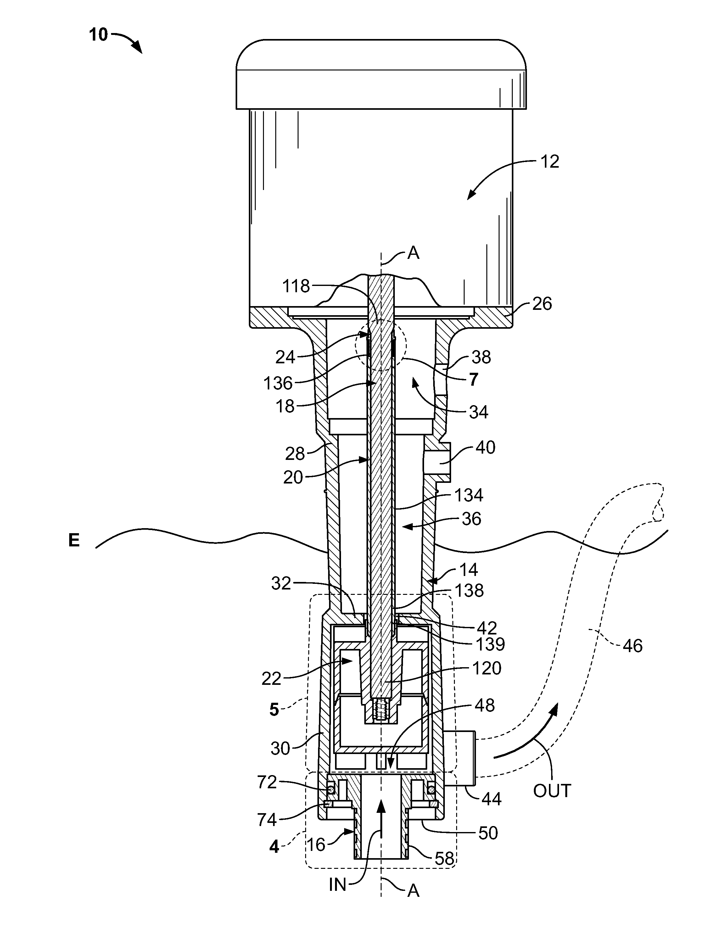
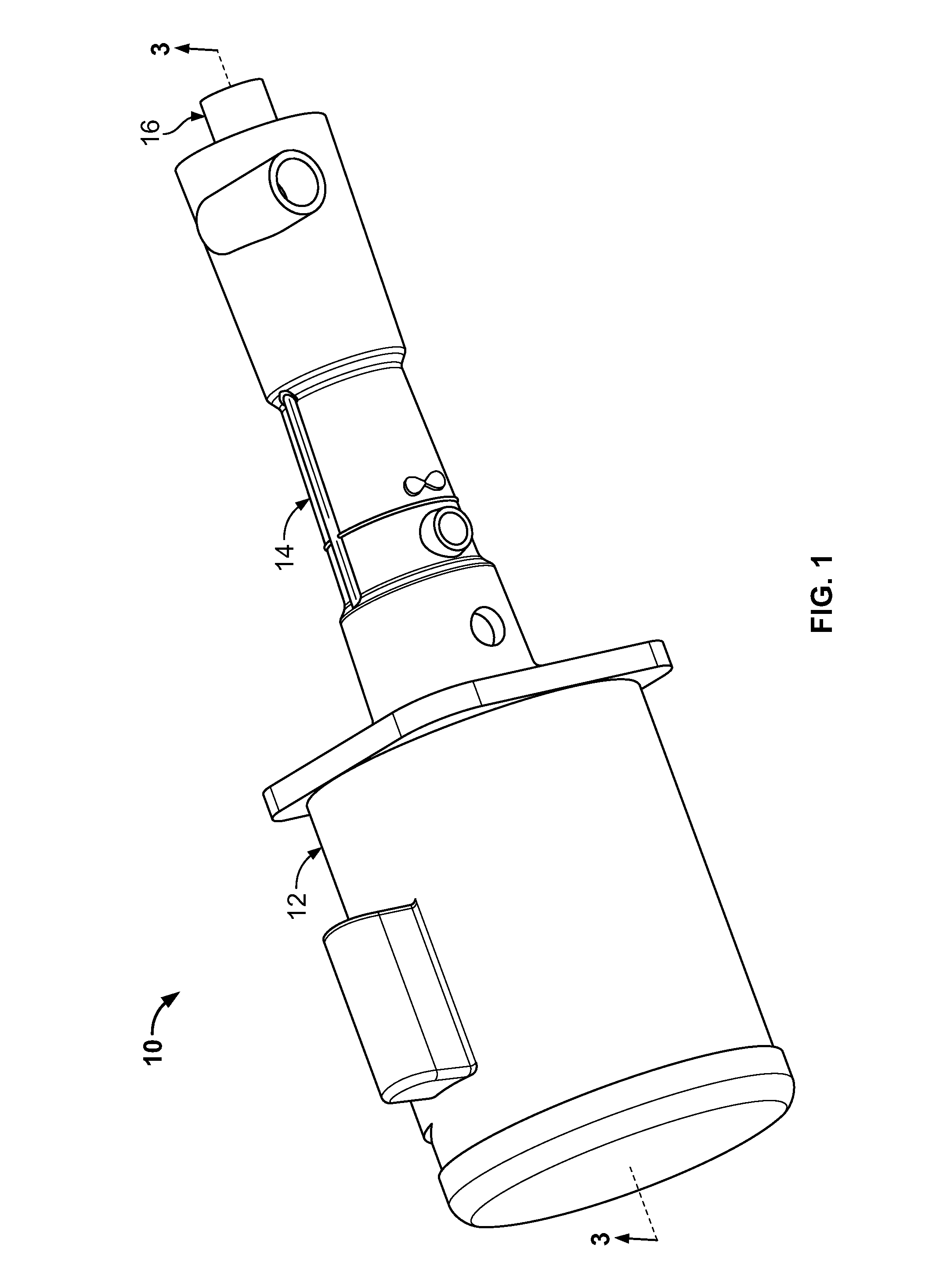
[0020]Referring to FIGS. 1-3, an immersible pump 10 is shown constructed in accordance with an exemplary embodiment of the present invention. The use of the word immersible should not be construed as requiring the reference device to be fully submerged in fluid. The immersible pump 10 includes a motor 12, an impeller housing 14, an end cap 16, a shaft 18, a shaft sleeve 20, an impeller 22, and a sealing device 24, each of which will be discussed with further detail below.

[0021]Referring to FIG. 3, the immersible pump 10 includes the impeller housing 14. The impeller housing 14 can be generally monolithic in form and includes an end plate 26, a first portion 28, a second portion 30, and a division wall 32 separating the first portion 28 and the second portion 30. The first portion 28 generally forms a first shaft chamber 34 and a second shaft chamber 36 for substantially housing a portion of the shaft 18, the shaft sleeve 20, and the sealing device 24. Extending through a wall of the...


PUM

PropertyMeasurementUnit
Forceaaaaaaaaaa
Diameteraaaaaaaaaa

Abstract

Disclosed herein is an apparatus for an immersible pump. The apparatus can include a shaft for communicating with a motor. The shaft includes a first region having a first diameter, a second region having a second diameter that is less than the first diameter, and a tapering region between the two regions. A sleeve can be provided to receive the shaft. A sealing device includes a receiving area in which the tapering region is at least partially positionable to form a seal, and an abutment that is configured to form a seal with the sleeve and that is responsive to a force directed from the sleeve to enhance the seal with the tapering region. In some embodiments, the sealing device is provided with a circumferential outer wall for centering the sleeve about the shaft and / or for aligning the force with the abutment.

Description

FIELD OF THE INVENTION[0001]The present invention relates generally to a shaft sealing device, and, more specifically, to a sealing device that is compressible between a shaft and a shaft sleeve for restricting fluidic access between the shaft and the shaft sleeve.BACKGROUND OF THE INVENTION[0002]Immersible pumps known in the art are utilized to pump fluid from a fluid source. Often, the fluid being pumped contains corrosive liquid chemicals. At least for reasons due to the corrosive nature of the fluid, it is desirous to keep the fluid away from metal components of the immersible pump, such as the shaft, for example. To achieve this, a non-metal sleeve is provided to cover the shaft and thus protect it from contacting the corrosive fluid. However, a small space remains between the shaft and the sleeve where fluid may enter. The prior art includes the use of an o-ring in an effort to restrict fluid entry. For example, reference is made to the prior art pump 500 of FIG. 11. The prior...

Claims


Application Information

Patent Timeline
IPC IPC(8): F04D29/12B23P11/00F04D13/02
CPCF04D13/08F04D29/106Y10T29/49243F04D29/043
Inventor STONE, JON TERENCEMOREN, GARY A.
Owner HAYWARD IND INC
Why Eureka
Try Eureka