Modular aortic arch prosthetic assembly and method of use thereof

Active Publication Date: 2018-06-07
MEDTRONIC VASCULAR INC
View PDF3 Cites 18 Cited by
  • Summary
  • Abstract
  • Description
  • Claims
  • Application Information

AI Technical Summary

Benefits of technology

[0047]With reference to FIG. 7, second branch stent-graft prosthesis 152 is configured for placement in a vessel such as the left common carotid artery or the left subclavian artery. Second branch stent-graft prosthesis 152 includes graft material 158 coupled to circumferential stents 160. Graft material 158 may be coupled to circumferential stents 160 using stitching or other means. In the embodiment shown in FIG. 7, circumferential stents 160 are coupled to an outside surface of graft material 158. However, circumferential stents 160 may alternatively be coupled to an inside surface of graft material 158. Although shown with five circumferential stents, it will be understood by one of ordinary skill in the art that second branch stent-graft prosthesis 152 may include a greater or smaller number of stents depending upon the desired length of second branch stent-graft prosthesis 152 and/or the intended application thereof. Graft material 158 may be any suitable graft material, for example and not limited to, woven polyester, DACRON® material, expanded polytetrafluoroethylene, polyurethane, silicone, or other suitable materials. Circumferential stents 160 may be any conventional stent material or configuration. As shown, circumferential stents 160 are preferably made from a shape memory material, such as nickel-titanium alloy (nitinol), and are formed into a zig-zag configuration. The configuration of circumferential stents 160 is merely exemplary, and circumferential stents 160 may have any suitable configuration known in the art, including but not limiting to a continuous or non-continuous helical configuration. Second branch stent-graft prosthesis 152 includes a proximal end 154 and a distal end 156. In an embodiment hereof, as shown in FIG. 7, both a proximal-most stent 160A and a distal-most stent 160B extend only to the edge of the graft material 158 in a closed-web configuration as shown. In another embodiment hereof, the proximal-most stent and/or distal-most stent may extend outside of the graft material 158 in an open-web or uncovered configuration. Further, as shown in FIG. 7, in an embodiment hereof proximal end 154 of second branch stent-graft prosthesis 152 is flared. The flared proximal end 154 aids in sealing of second branch stent-graft prosthesis 152 by matching the flare thereof with the taper of the outer surface of coupling 132 of distal aortic stent-graft prosthesis 122. Graft material 158 has a tubular configuration and as such defines a lumen 159 therethrough. Second branch stent-graft prosthesis 152 may be similar to the Medtronic, Inc.'s VALIANT® thoracic stent-graft, or other known stent-grafts.
[0048]Although not shown, in another embodiment hereof, proximal end 144 of first branch stent-graft prosthesis 142 may also be flared similar to proximal end 154 of

Problems solved by technology

As will be explained in more detail herein, the distance(s) between the great branch vessels varies considerably amongst patients and the anatomical variation of the aortic arch complicates treatment thereof.
Such surgery is highly invasive, requires an extended recovery period and, therefore cannot be performed on individuals in fragile health or with other contraindicative factors.
The use of stent-grafts to internally bypass, within the aorta or flow lumen, the aneurysmal site, is also not without challenges.
As a result, blood leakage is prone to occur into the space between the outer surface of the main aortic stent-graft and the surrounding aortic wall between the edge of the graft material surrounding the fenestrations and the adjacent vessel wall.
Similar blood leakage can result from post-implantation migration or movement of the stent-graft causing misalignment between the fenestration(s) and the branch artery(ies), which may also result in impaired flow into the branch artery(ies).
This connection between the branch stent-graft and main stent-g

Method used


Image

  • Modular aortic arch prosthetic assembly and method of use thereof
  • Modular aortic arch prosthetic assembly and method of use thereof
  • Modular aortic arch prosthetic assembly and method of use thereof

Examples


Embodiment Construction

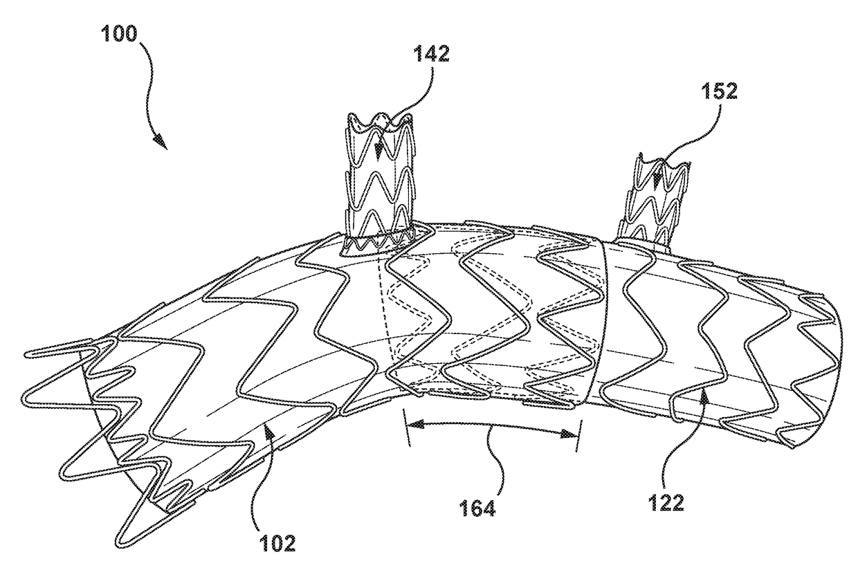
[0031]Specific embodiments are now described with reference to the figures, wherein like reference numbers indicate identical or functionally similar elements. Unless otherwise indicated, for the delivery system the terms “distal” and “proximal” are used in the following description with respect to a position or direction relative to the treating clinician. “Distal” and “distally” are positions distant from or in a direction away from the clinician, and “proximal” and “proximally” are positions near or in a direction toward the clinician. For the stent-graft devices “proximal” is the portion nearer the heart by way of blood flow path while “distal” is the portion of the stent-graft further from the heart by way of blood flow path.

[0032]The following detailed description is merely exemplary in nature and is not intended to limit the invention or the application and uses of the invention. Although the description of embodiments hereof is primarily in the context of modular devices for...


PUM


Abstract

A prosthetic assembly configured for endovascular placement within an aortic arch and method of use thereof. The prosthetic assembly includes a proximal aortic stent-graft prosthesis configured to be positioned within a proximal portion of the aortic arch adjacent to the brachiocephalic artery, a distal aortic stent-graft prosthesis configured to be positioned within a distal portion of the aortic arch adjacent to the left subclavian artery, a first branch stent-graft prosthesis configured to be positioned within the brachiocephalic artery and a second branch stent-graft prosthesis configured to be positioned in one of the left common carotid and the left subclavian artery. When deployed, a proximal end of the first branch stent-graft prosthesis is disposed within a lumen of the proximal aortic stent-graft prosthesis to proximally displace the ostium of the brachiocephalic artery. When deployed, a proximal end of the distal aortic stent-graft prosthesis is disposed within the distal end of the proximal aortic stent-graft prosthesis to form an overlap between the proximal and distal aortic stent-graft prostheses. The overlap is relatively increased by the first branch stent-graft prosthesis proximally displacing the ostium of the brachiocephalic artery.

Description

CROSS REFERENCE TO RELATED APPLICATIONS[0001]This application claims the benefit under 35 U.S.C. § 119(e) of the filing date of U.S. Provisional Application No. 62 / 430,218 filed Dec. 5, 2016, the contents of which are incorporated by reference herein, in their entirety.FIELD OF THE INVENTION[0002]This invention relates generally to endoluminal medical devices and procedures, and more particularly to a modular assembly or system configured to perfuse the aortic arch via an endovascular approach.BACKGROUND OF THE INVENTION[0003]Aneurysms, dissections, penetrating ulcers, intramural hematomas and / or transections may occur in blood vessels, and most typically occur in the aorta and peripheral arteries. Depending on the region of the aorta involved, the aneurysm may extend into areas having vessel bifurcations or segments of the aorta from which smaller “branch” arteries extend. Various types of aortic aneurysms may be classified on the basis of the region of aneurysmal involvement. For ...

Claims


Application Information

Patent Timeline
IPC IPC(8): A61F2/07A61F2/852
CPCA61F2/07A61F2/852A61F2210/0014A61F2/954A61F2250/0098A61F2002/826A61F2002/067A61F2002/061A61F2002/075A61F2002/068A61F2250/0063A61F2250/0065A61F2250/0039
Inventor PERKINS, KEITHBROOKS, DENNISSTIGER, MARK
Owner MEDTRONIC VASCULAR INC
Why Eureka
Try Eureka