Method of expanding a tubular element in a wellbore

Inactive Publication Date: 2013-04-30
SHELL OIL CO
View PDF10 Cites 3 Cited by
  • Summary
  • Abstract
  • Description
  • Claims
  • Application Information

AI Technical Summary

Benefits of technology

The patent describes a method to expand a tubular section in a wellbore without using an expander. The process involves moving the remaining tubular section downward to turn it inside out and expand it without needing another device. To ensure a better seal with the wellbore wall, the load transfer means exerts a radially outward pressure on the expanded tubular section. To induce the movement of the remaining tubular section, an axially compressive force is applied to it, which results from the weight of the section and may be supplemented by an external force. As the length of the remaining tubular section increases, an upward force may be needed to prevent uncontrolled bending or buckling in the bending zone. The technique may offer an alternative to traditional expanders and may improve wellbore stability.

Problems solved by technology

As a result, the cross-sectional wellbore size that is available for oil and gas production, decreases with depth.
Such method can lead to high friction forces between the expander and the tubular element.
Also, there is a risk that the expander becomes stuck in the tubular element.

Method used


Image

  • Method of expanding a tubular element in a wellbore
  • Method of expanding a tubular element in a wellbore
  • Method of expanding a tubular element in a wellbore

Examples


first embodiment

[0030]Referring to FIG. 4 there is shown the first embodiment during drilling of the wellbore 1 whereby a drill string 26 extends from surface 6 through the unexpanded liner section 8 to the bottom of the wellbore 1. The drill string 26 is at its lower end provided with a drill bit 27 comprising a pilot bit 28 with gauge diameter slightly smaller than the internal diameter of the unexpanded liner section 8, and a reamer section 30 with gauge diameter adapted to drill the wellbore 1 to its nominal diameter. The reamer section 30 is radially retractable to an outer diameter allowing it to pass through unexpanded liner section 8, so that the drill string 26 can be retrieved through the unexpanded liner section 8 to surface.

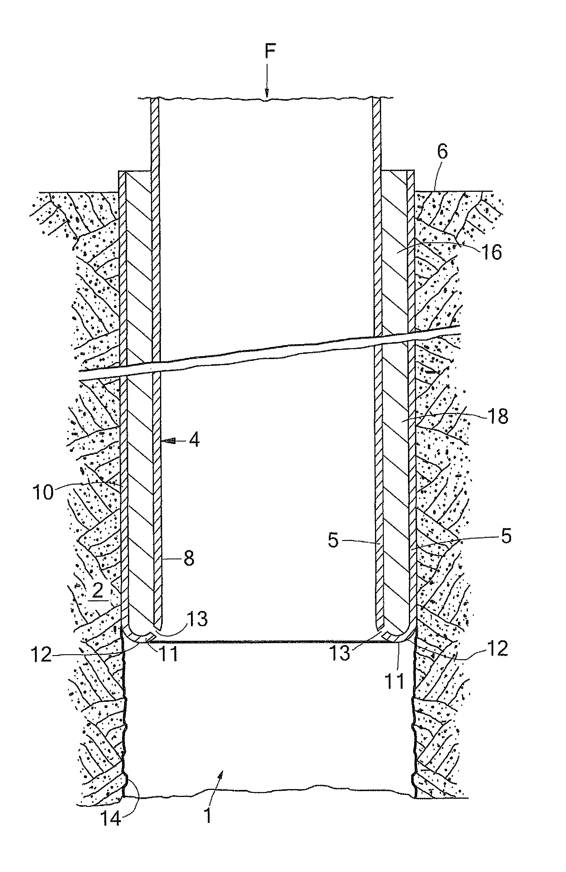
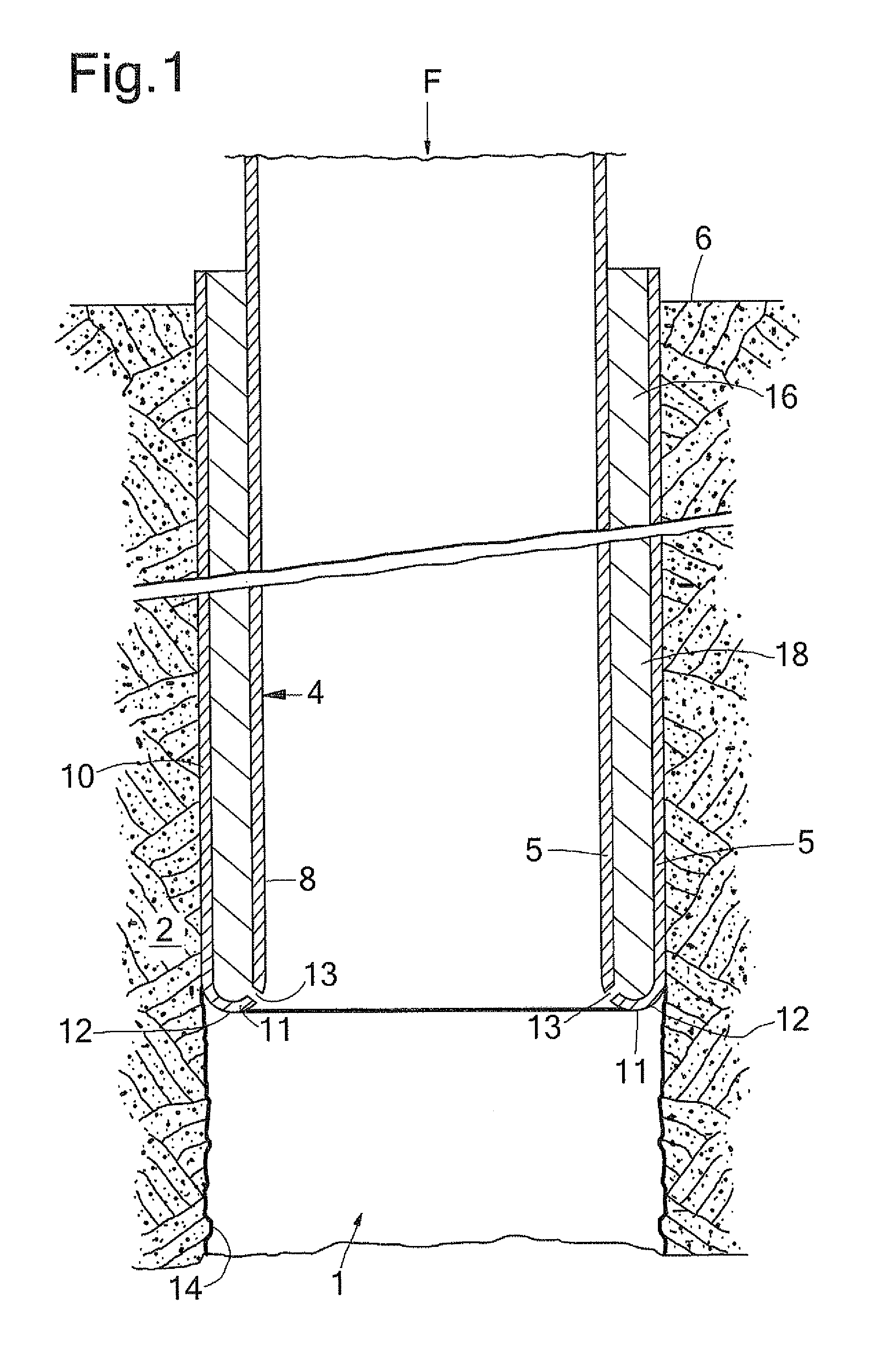
[0031]During normal operation of the first embodiment (FIG. 1), a lower end portion of the liner 4 is initially everted. That is, the lower portion is bent radially outward and in axially reverse direction. The U-shaped lower section 11 and the expanded liner section...

third embodiment

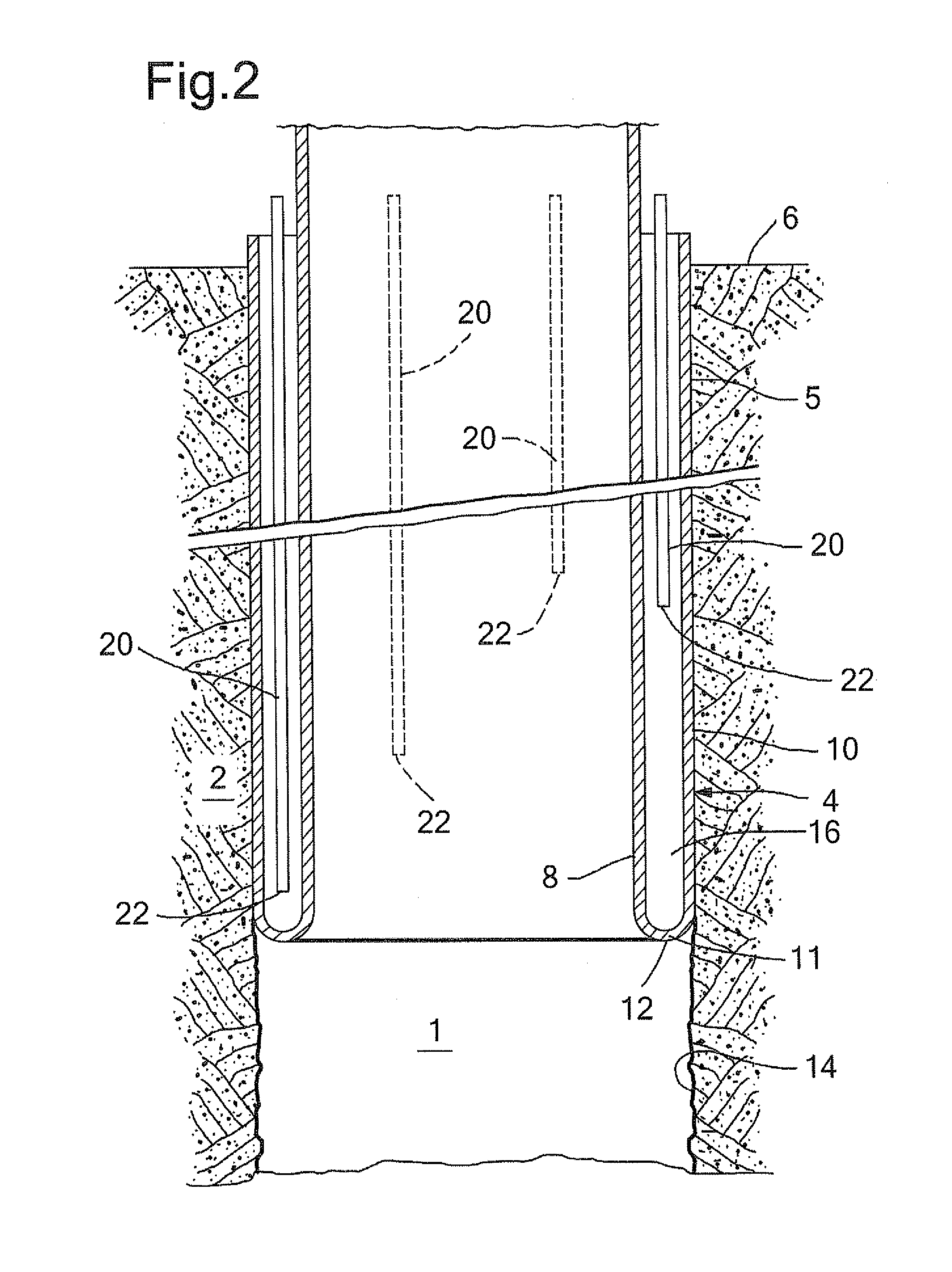
[0046]In a modified version of the third embodiment, the annular support members are arranged to move, together with the liner wall, through the bending zone. Thus, after eversion the annular support members are fixedly connected to the expanded liner section and extend against the unexpanded liner section.

[0047]Instead of expanding the expanded liner section against the wellbore wall (as explained in the detailed description), the expanded liner section can be expanded against the inner surface of another tubular element already present in the wellbore.


PUM


Abstract

A method of radially expanding a tubular element in a wellbore formed in an earth formation comprises arranging the tubular element in the wellbore such that a lower end portion of the wall of the tubular element extends radially outward and in an axially reverse direction so as to form an expanded tubular section extending around a remaining tubular section of the tubular element, whereby an annulus is defined between the expanded and remaining tubular sections. The expanded tubular section is axially extended by moving the remaining tubular section downward relative to the expanded tubular section so that the lower end portion of the wall bends radially outward and in an axially reverse direction, and load transfer means is positioned in the annulus, the load transfer means being arranged to transfer a load between the remaining tubular section and the expanded tubular section.

Description

PRIORITY CLAIM[0001]The present application claims priority to PCT Application EP2008 / 066296, filed 24 Dec. 2008, which in turn claims priority from European Application EP08100118.2, filed 4 Jan. 2008.TECHNICAL FIELD OF THE INVENTION[0002]The present invention relates to a method of radially expanding a tubular element in a wellbore formed into an earth formation.BACKGROUND OF THE INVENTION[0003]The technology of radially expanding tubular elements in wellbores finds increasing application in the industry of oil and gas production from subterranean formations. Wellbores are generally provided with one or more casings or liners to provide stability to the wellbore wall, and / or to provide zonal isolation between different earth formation layers. The terms “casing” and “liner” refer to tubular elements for supporting and stabilising the wellbore wall, whereby it is generally understood that casing extends from surface into the wellbore and that a liner extends from a certain depth fur...

Claims


Application Information

Patent Timeline
IPC IPC(8): E21B19/00
CPCE21B7/20E21B43/103F16L55/164F16L55/1651
Inventor VAN NIEUWKOOP, PIETER
Owner SHELL OIL CO
Why Eureka
Try Eureka