Distributed antenna system using power-over-ethernet

a technology of ethernet cables and antennas, applied in the field of telecommunications, can solve the problems of devices having different power needs or demands, and achieve the effects of increasing power, increasing power level, and increasing power level

Active Publication Date: 2012-12-13
COMMSCOPE TECH LLC
View PDF10 Cites 168 Cited by
  • Summary
  • Abstract
  • Description
  • Claims
  • Application Information

AI Technical Summary

Benefits of technology

[0010]Another aspect is a system that includes a powered device, power sourcing equipment, a channel, and a sub-system. The power sourcing equipment can provide power to the powered device. The channel can couple the power sourcing equipment to the powered device. The sub-system can include at least one measurement device and a processor. The measurement device can measure an output voltage of the power sourcing equipment, measure an input voltage of the powered device, and measure a current on the channel. The processor can be communicatively coupled to the power sourcing equipment. The processor can determine the resistance of the channel based on the output voltage, the input voltage, and the current. The processor can determine, based on the resistance of the channel, an amount by which to increase a level of power provided to the powered device. The processor can output a command to the power sourcing equipment to increase the level of power and the amount by which to increase the level of power.

Problems solved by technology

As telecommunications devices adapt to meet new communication demands, however, such devices may have different power needs or demands.

Method used


Image

  • Distributed antenna system using power-over-ethernet
  • Distributed antenna system using power-over-ethernet
  • Distributed antenna system using power-over-ethernet

Examples


Embodiment Construction

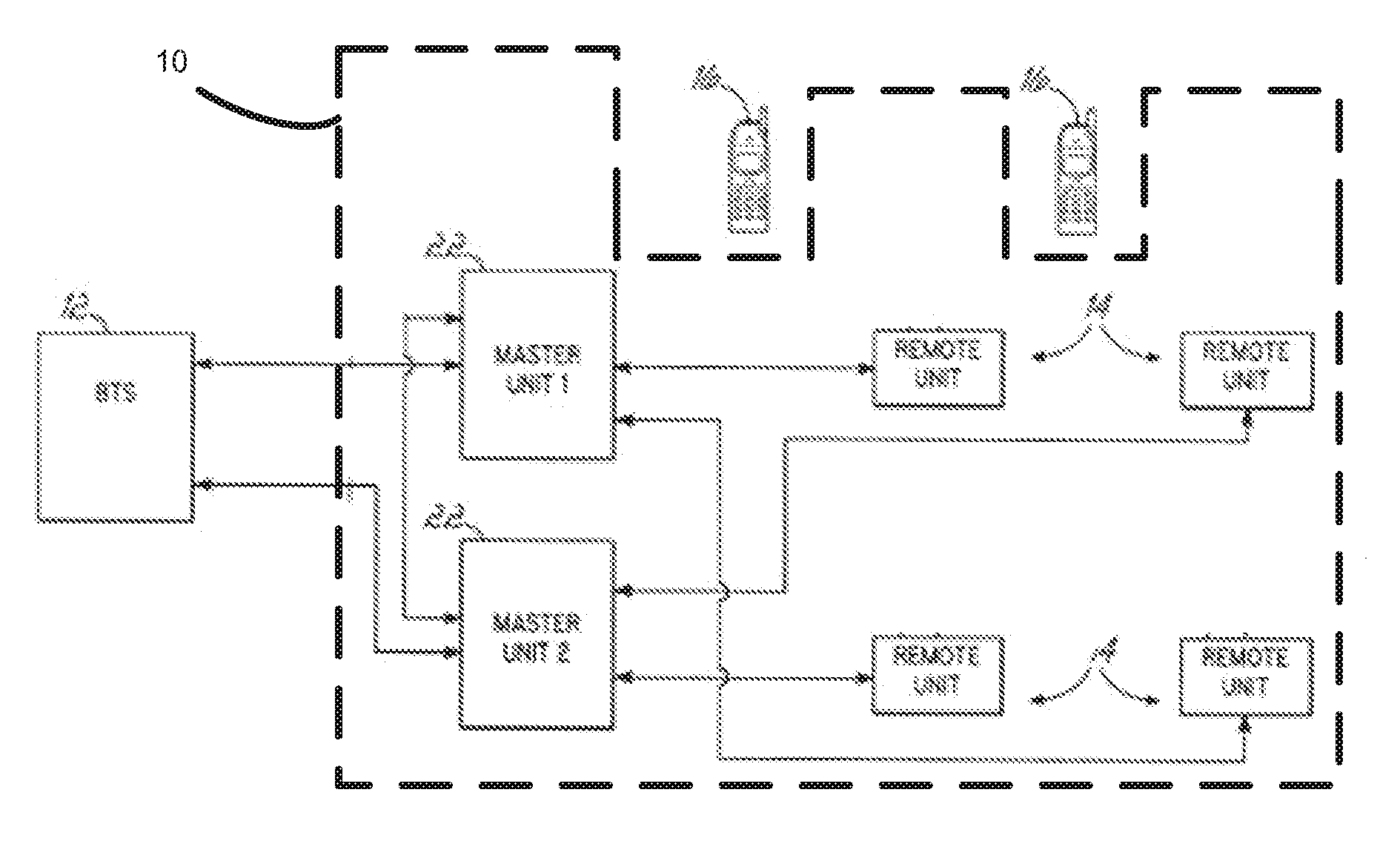
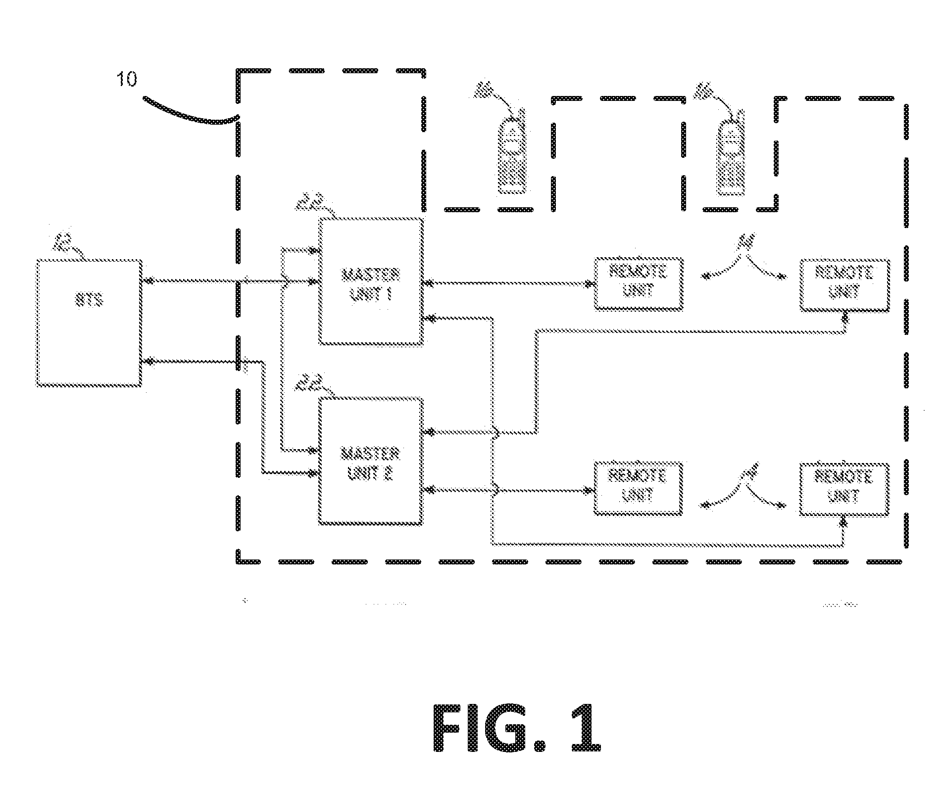
[0020]Certain aspects and features of the present invention are directed to a PoE system for a distributed antenna system (“DAS”). A DAS can include a master unit communicating telecommunication information between base stations or other equipment of cellular service providers and remote antenna units distributed in an area and capable of wirelessly communicating with wireless devices. Power can be delivered via PoE from power source equipment (“PSE”), which may be in a master unit, to a powered device (“PD”), which may be in a remote antenna unit.

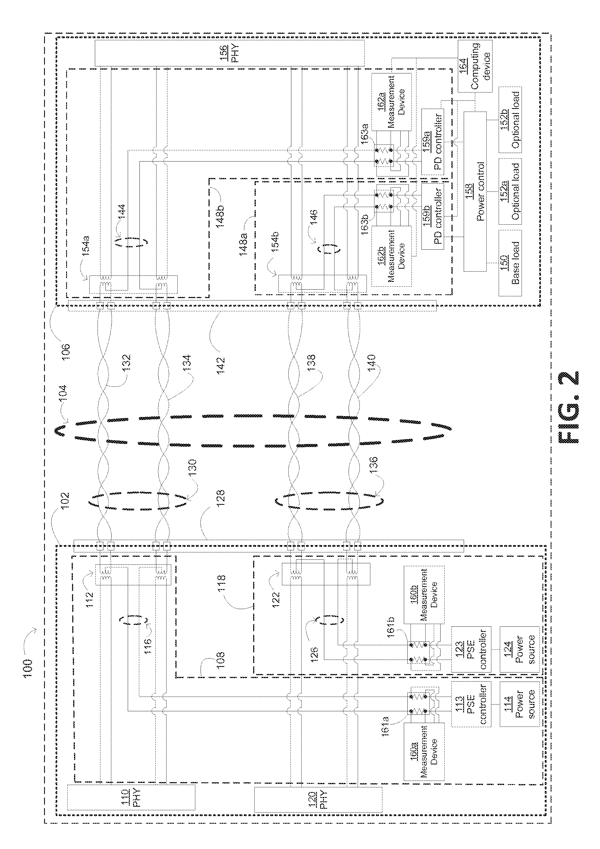
[0021]A PoE system according to some aspects may also include a system for adjusting the power provided by a PSE to one or more PDs based on the resistance of a channel that includes an Ethernet cable coupling the PSE to one or more of the PDs. The PoE system can include hardware and / or software for adjusting power supplied by the PSE. The hardware and / or software for adjusting power supplied by the PSE may be disposed in the PSE, in the P...


PUM


Abstract

A system is provided for adjusting power provided to a device. The system can include power sourcing equipment and a sub-system. The power sourcing equipment can provide power to a powered device via a channel. The sub-system can determine an amount by which to increase the power based on a resistance of the channel. The power sourcing equipment or the powered device can adjust the power (or load) responsive to a command from the sub-system. The sub-system can include a measurement device and a processor. The measurement device can measure an output voltage of the power sourcing equipment, an input voltage of the powered device, and a current on the channel. The processor can determine the resistance of the channel based on the output voltage, the input voltage, and the current. The processor can output a command specifying an increase or decrease in power supplied by the power sourcing equipment.

Description

CROSS-REFERENCE TO RELATED APPLICATIONS[0001]This application claims priority to U.S. Provisional Application Ser. No. 61 / 495,067 filed Jun. 9, 2011 and titled “Distributed Antenna System Using Power-Over-Ethernet,” the contents of which are hereby incorporated by reference.TECHNICAL FIELD[0002]The present invention relates generally to telecommunications and more particularly (although not necessarily exclusively) to a method and system for delivering power over Ethernet cables.BACKGROUND[0003]Numerous powered devices utilize power over multi-pair Ethernet cables. The IEEE 802.3at-2009 Power-over-Ethernet (“PoE”) standard, ratified Sep. 11, 2009, defines a standardized approach for providing power over Ethernet cables.[0004]A non-limiting example of an Ethernet cable is a category 5 cable. A category 5 cable includes eight wire connectors grouped into four wire pairs. Under the IEEE 802.3at-2009 PoE standard, power sourcing equipment can provide DC power over two of the four wire p...

Claims


Application Information

Patent Timeline
Patent Type & Authority Applications(United States)
IPC IPC(8): G06F1/26
CPCH04L12/10H04L41/0833H04L12/40045G06F1/28
Inventor HUNTER, JR., ROGER A.MCALLISTER, DONALD ROBERTRANSON, CHRISTOPHER G.KUMMETZ, THOMAS
Owner COMMSCOPE TECH LLC
Why Eureka
Try Eureka