Wiper blade of flat beam construction

a technology of flat beam and blade, which is applied in the direction of vehicle maintenance, vehicle cleaning, domestic applications, etc., can solve the problem of lowering achieve the effect of reducing the risk of faulty mounting operations, short time, and simple manual maneuvering

Active Publication Date: 2012-12-20
ROBERT BOSCH GMBH
View PDF8 Cites 9 Cited by
  • Summary
  • Abstract
  • Description
  • Claims
  • Application Information

AI Technical Summary

Benefits of technology

[0004]The wiper blade according to the invention with the connection element and its fixing element forms a simple plug-in system, in which the mounting can be carried out by simple manual maneuvers in a short time. Furthermore, the risk of faulty mounting operations is lowered by the simplified mounting. The fixing element itself is a dimensionally stable component which transmits the forces which act on it to the connection element over a large surface area and without play. The surface pressures which are relevant for the wear are very low. It can therefore take over further functions; for example, it can receive bearing elements for the articulated connection to a wiper arm. To this end, in its side walls, the fixing element advantageously has holes which serve as a hub or to receive a pivot pin. If the pivot pin is riveted into the side walls of the fixing element, the connection element has cutouts in the region of the outwardly projecting rivet heads, into which cutouts the rivet heads engage during the mounting. In order to anchor the fixing element in the connection element it is clipped virtually without play into the recesses of the connection element or is inserted from open sides of the recess which lies facing away from the wiping strip, and is latched by latching lugs in the recesses of the side walls, which latching lugs latch into latching openings of the side walls of the fixing element during the mounting.
[0005]In principle, the connection element and the fixing element can be produced from plastic. However, the fixing element is expediently manufactured from metal, in order to achieve greater strength, stability and service life. As a result, satisfactory lateral guidance and high wiping quality are ensured over the service life of the wiper blade. In an advantageous way, the fixing element made from metal is combined with a connection element made from plastic.

Problems solved by technology

Furthermore, the risk of faulty mounting operations is lowered by the simplified mounting.

Method used


Image

  • Wiper blade of flat beam construction
  • Wiper blade of flat beam construction
  • Wiper blade of flat beam construction

Examples


Embodiment Construction

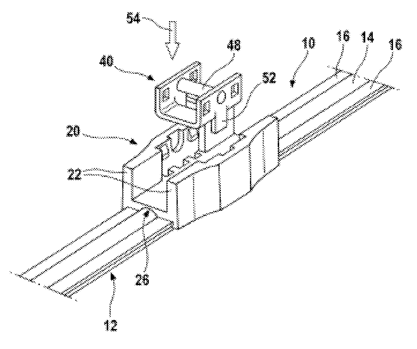
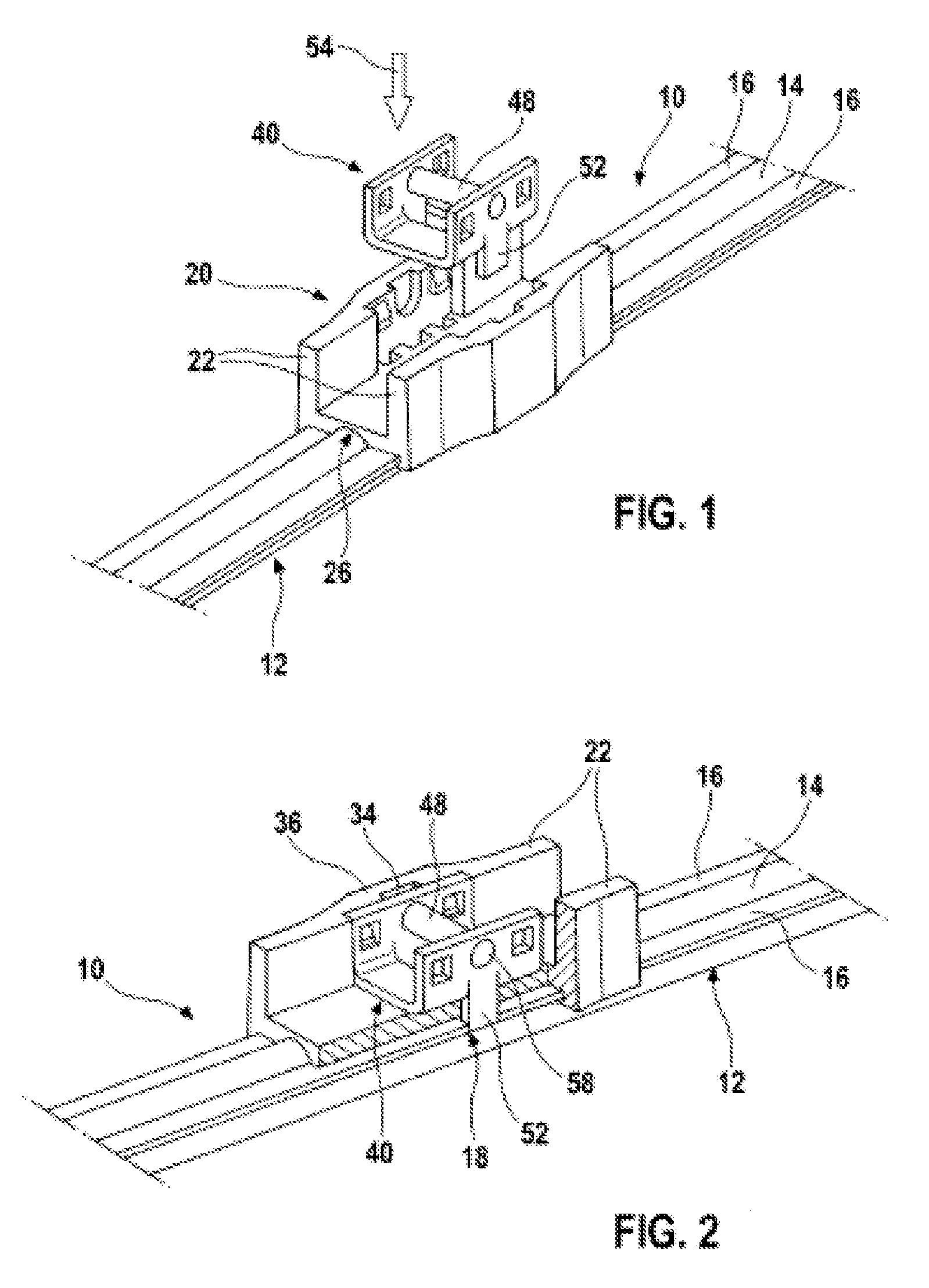
[0014]A wiper blade 10 substantially has a wiper strip 12, the rear strip 14 of which is held by two spring bars 16 which engage as a carrying element below the rear strip 14 into longitudinal grooves (not shown in greater detail) of the wiper strip 12. Solutions are also possible with a spring bar 16 which as a rule is accommodated in a longitudinal channel of the wiper strip 12. A connection element 20 which serves for the articulated connection of the wiper blade 10 to a wiper arm (not shown) is fastened on the spring bars 16 in the central region of the wiper blade 10.

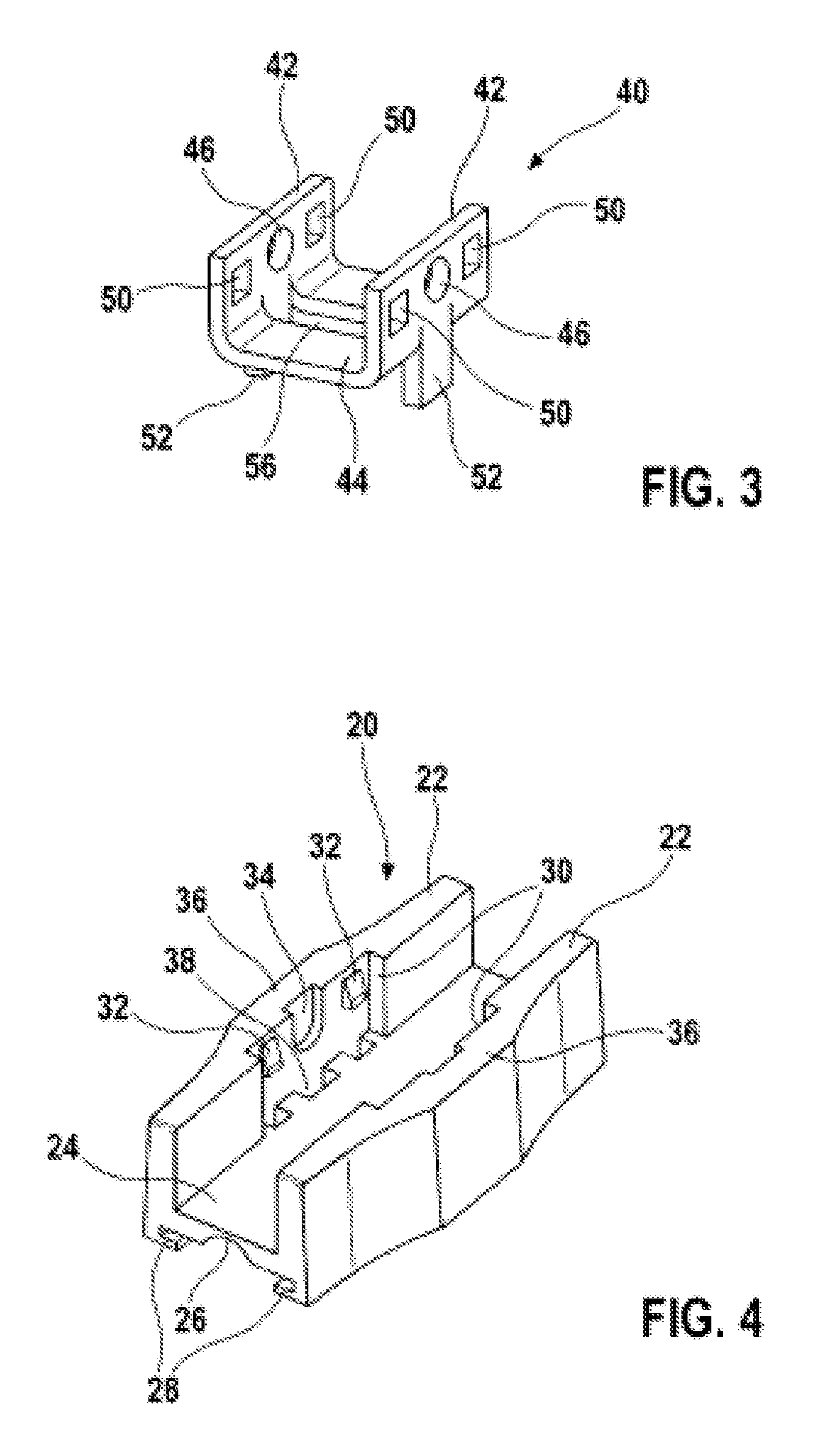
[0015]The connection element 20 has two side walls 22 which have guide profiles 28 toward the spring bars 16. In the mounted state, they clasp the spring bars 16 laterally from below and from above. The two side walls 22 of the connection element 20 are connected to one another above the guide profiles 28 by a base 24. Toward the wiper strip 12, said base 24 has a longitudinal groove 26 which affords sufficient spa...


PUM


Abstract

The invention is based on a wiper blade (10) of flat beam construction having a support element in the form of at least one pre-bent spring rail (16) to which is fastened, in the central region, a connecting element (20) for articulatedly connecting to a wiper arm, wherein the connecting element (20) has two side walls (22) with open guide profiles (28), facing toward one another, for the spring rail (16), the side walls (22) are connected to one another by means of transversely running parts (24), and the connecting element (20) is fixed relative to the spring rail (16) in the longitudinal direction by means of a fixing element (40), wherein the fixing element (40) engages into cutouts (34) on the outer longitudinal sides of the spring rail (16). It is proposed that the fixing element (40) has a U-shaped cross-sectional profile with two side walls (42) which are connected to one another by means of a base (44) and which are sunk into recesses (30) on the inner sides of the side walls (22) of the connecting element (20), wherein the base (44) of the fixing element (40) runs parallel to the base (24) of the connecting element (20), and lugs (52) are connected to the side walls (42) of the fixing element (40) as an elongation of the side walls (42) toward the spring rail (16), which lugs (52) engage into the cutouts (34) of the spring rail (16) through openings (38) in the base (24) of the connecting element (20).

Description

BACKGROUND OF THE INVENTION[0001]The invention proceeds from a wiper blade of flat beam construction.[0002]DE 100 58 208 A1 has disclosed a wiper blade of the generic type, in which a connection element made from a suitable material, for example from plastic, is fastened in the central region on two spring bars which run in parallel and serve as a carrying element. On the longitudinal sides, the connection element has guide profiles, by way of which it clasps the spring bars from the outer longitudinal sides at the top and bottom, and on the longitudinal sides themselves. Between the two spring bars, there is a fixing element which is supported on the connecting element and fixes the spring bars in a positive and / or nonpositive manner. A pin is provided as fixing element, which pin is guided approximately perpendicularly with respect to the lateral side of the spring bars in a hole of the connection element and presses the spring bars nonpositively to the outside against the guide p...

Claims


Application Information

Patent Timeline
Patent Type & Authority Applications(United States)
IPC IPC(8): B60S1/40
CPCB60S1/387B60S1/3858B60S2001/4093
Inventor BENNER, ANDREASWESTERMANN, KLAUS-JUERGENWESTERMANN, URSULA
Owner ROBERT BOSCH GMBH
Why Eureka
Try Eureka