Internal air circulation control in a refrigerated transport container

a technology for refrigerated transport containers and air circulation control, which is applied in the direction of refrigerators/freezers, refrigeration devices, sustainable buildings, etc., can solve the problems of hardware damage, energy consumption is not efficient, and the risk of increasing the temperature distribution throughout the container's transport volume, so as to minimize the risk of temperature-abuse, and save energy

Inactive Publication Date: 2012-12-20
MAERSK LINE AS
View PDF11 Cites 46 Cited by
  • Summary
  • Abstract
  • Description
  • Claims
  • Application Information

AI Technical Summary

Benefits of technology

[0093]In this way, emphasis on minimizing temperature distribution in the transport volume is provided and gives up the effort to save energy in specific temperature setpoint ranges. Th

Problems solved by technology

In connection with evaporator fan systems having only two states (ON, OFF) and switching between these two states, energy usage is not efficient as the power consumption of a fan system is proportional to the third power of the air flow velocity generated by the fan system.
Would this fan speed reduction be done regardless of heat load then it would carry the risk of increasing temperature distribution throughout the container's transport volume.
Too many evaporator fan speed changes would carry the risk of hardware dama

Method used


Image

  • Internal air circulation control in a refrigerated transport container
  • Internal air circulation control in a refrigerated transport container
  • Internal air circulation control in a refrigerated transport container

Examples


Embodiment Construction

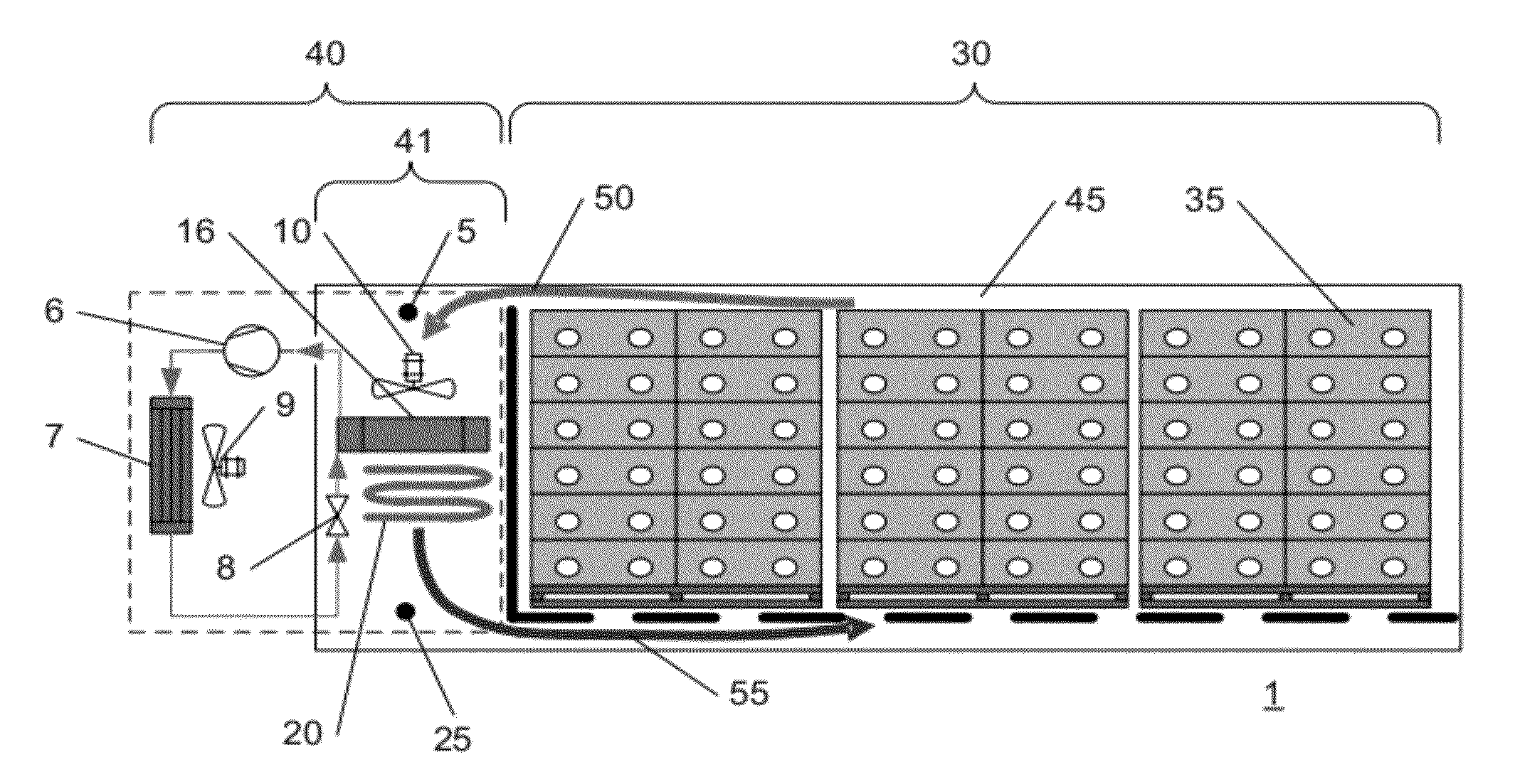
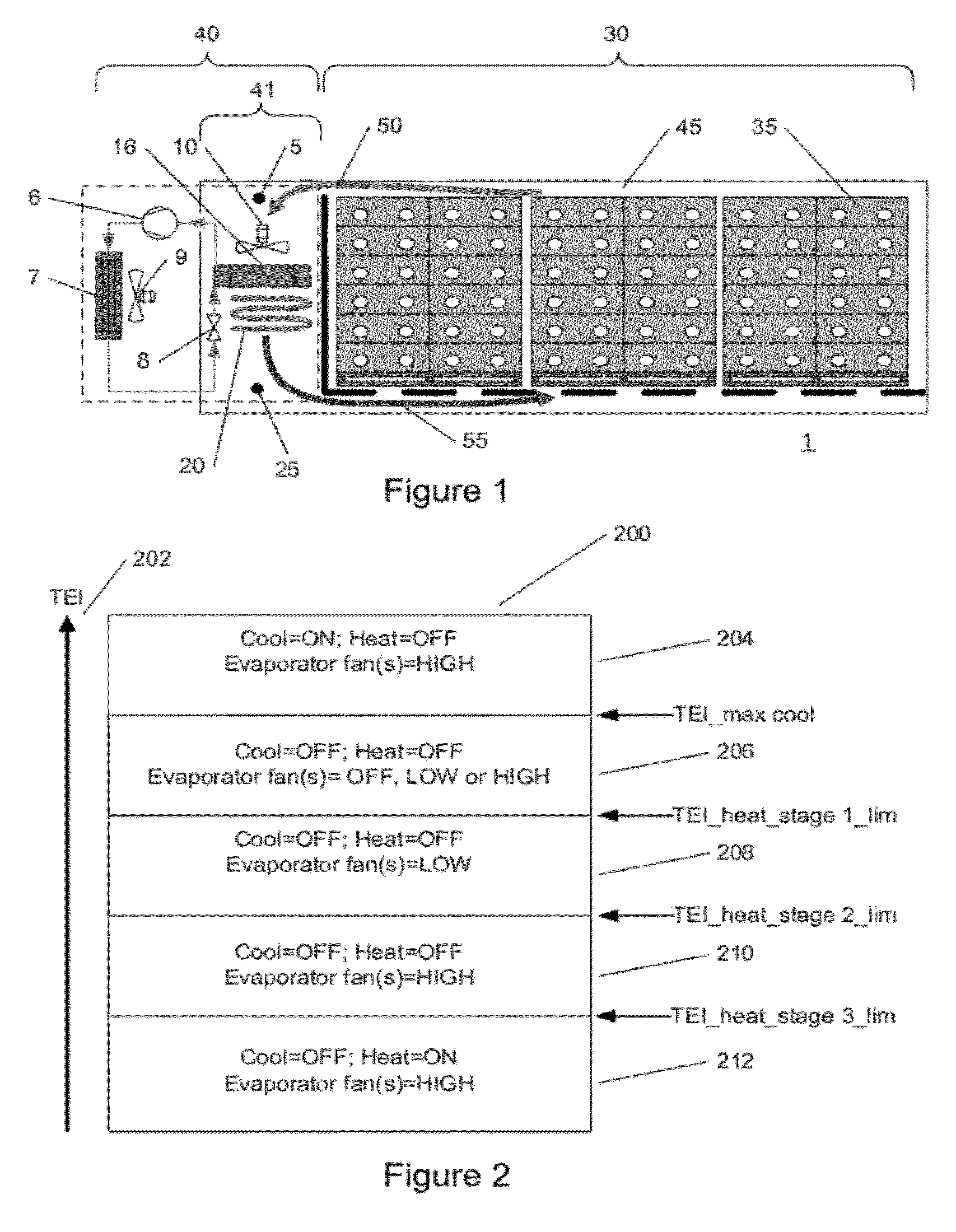
[0108]FIG. 1 is a simplified side cross-sectional view of a refrigerated transport container. FIG. 1 illustrates one example of a refrigerated transport container 1 wherein the described fan speed control method and / or system may be used. The fan speed control method and / or system may also be used in connection with other refrigerated spaces connected with a refrigeration unit. In the present specification, the term “fan speed” means evaporator fan speed.

[0109]FIG. 1 illustrates a refrigerated transport container 1 comprising a frontal section having a refrigeration unit or system 40 and a load or cargo section 30. The load or cargo section 30 of the refrigerated transport container 1 comprises a commodity load e.g. comprising a plurality of stackable transport boxes 35 arranged within a transport volume 45 such as to leave appropriate clearance at a ceiling and a floor structure for air flow passages above and beneath the commodity load.

[0110]The refrigeration unit 40 in this examp...


PUM


Abstract

Disclosed is a system for and a method of controlling internal air circulation within a refrigerated transport container (1), the refrigerated transport container (1) comprising a cooling unit (40), and a control unit, where the cooling unit (40) comprises at least a compressor (6) and an evaporator (16) comprising one or more evaporator fans (10) wherein the method comprises the step of: controlling the operation of the one or more evaporator fans (10) based on one or more predetermined heat load related indicators during periods where the compressor (6) is inactive wherein the one or more evaporator fans (10) are controlled to increase internal air circulation when the one or more predetermined heat load related indicators indicate a heat load increase and wherein the one or more evaporator fans (10) are controlled to decrease internal air circulation when the one or more predetermined heat load related indicators indicate a heat load reduction.

Description

[0001]Disclosed is a method for and system of controlling internal air circulation within a refrigerated transport container.BACKGROUND OF THE INVENTION[0002]Temperature in a refrigerated storage space is controlled within a temperature range adjacent to a setpoint temperature. The refrigerated storage space may for example comprise a transport volume of a refrigerated transport container. The setpoint temperature is chosen to keep the perishable produce such as meat, vegetables and fruit, at correct temperatures to avoid quality degradation. It is known in the art to apply temperature control protocols that selectively control operational states of heating units, cooling devices and evaporator fans, coupled to the refrigerated transport container, in order to maintain a setpoint or target air temperature inside the refrigerated transport container.[0003]One typical cooling unit or refrigeration unit used in refrigerated storage transport containers is based on the so-called vapour ...

Claims


Application Information

Patent Timeline
IPC IPC(8): F25D17/06F25B49/00
CPCF25B49/02F25B2600/112F25B2700/21172Y02B40/32Y02B30/743F25D11/003F25B2700/21173Y02B30/70Y02B40/00
Inventor LUKASSE, LEIJN JOHANNES SJERPDE KRAMER-CUPPEN, JANNEKE EMMY
Owner MAERSK LINE AS
Why Eureka
Try Eureka