Electric charging system and electric vehicle

a charging system and electric vehicle technology, applied in the direction of electric devices, transportation and packaging, propulsion by batteries/cells, etc., to achieve the effect of ensuring safety

Active Publication Date: 2012-12-20
SUBARU CORP
View PDF3 Cites 65 Cited by
  • Summary
  • Abstract
  • Description
  • Claims
  • Application Information

AI Technical Summary

Benefits of technology

[0020]According to the present invention, under a state in which a weld failure occurs at the relay unit, the warning unit issues a warning when the power receiving connector is not connected to the power supply connector under a state where a weld failure occurs at the relay unit and stops issuing a warning when the power receiving connector is connected to the power supply connector under a state where a weld failure occurs at the relay unit. In other words, a warning is stopped under a state in which the power receiving connector is covered with the power supply ...

Problems solved by technology

Furthermore, under a state in which a weld failure occurs at the relay unit and the power receiving connector is not covered by the cover, the warning unit issues a warning when...

Method used


Image

  • Electric charging system and electric vehicle
  • Electric charging system and electric vehicle
  • Electric charging system and electric vehicle

Examples


Embodiment Construction

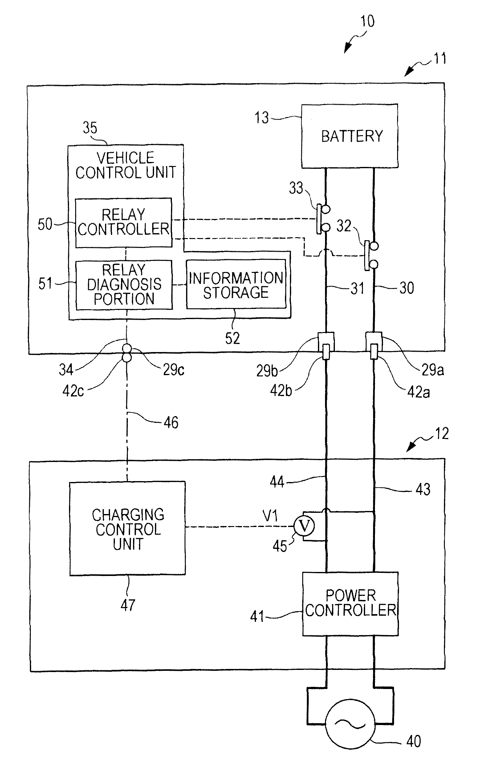
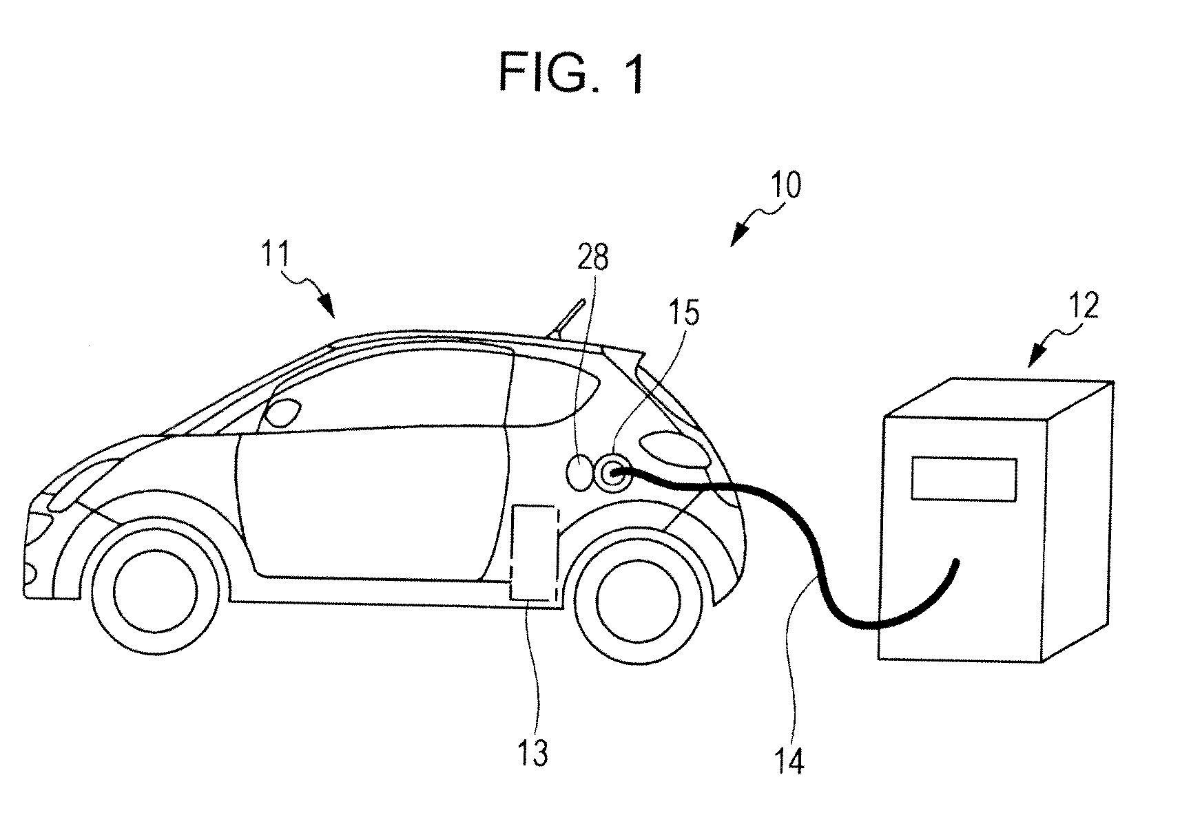
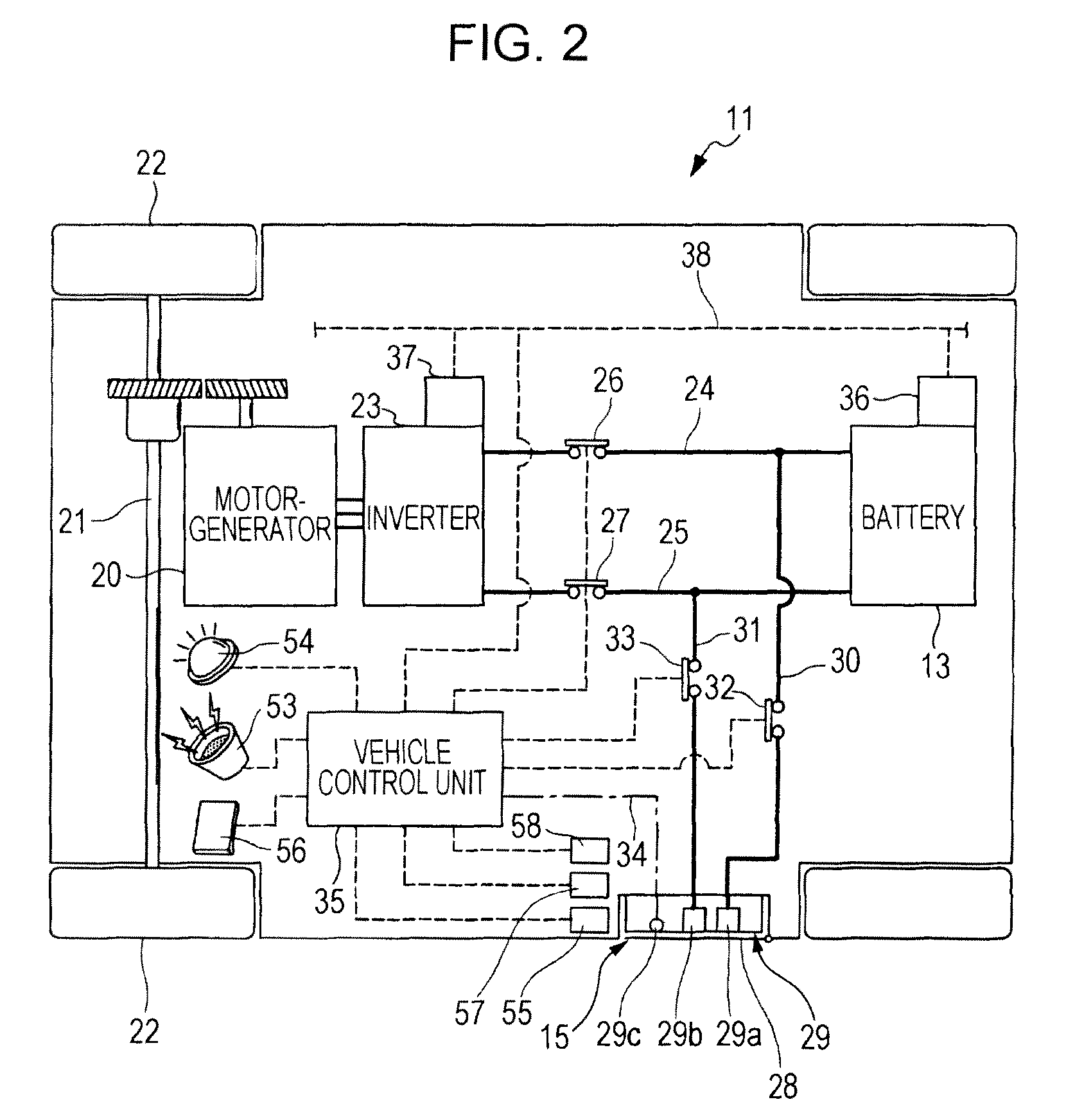
[0038]An embodiment of the present invention will hereunder be described with reference to the drawings. FIG. 1 is an explanatory diagram showing a case in which charging is preformed with an electric charging system 10 according to an embodiment of the present invention. FIG. 2 is a schematic diagram showing an internal structure of an electric vehicle 11 constituting the electric charging system 10. FIG. 3 is a schematic diagram showing an internal structure of an electric charger 12 constituting the electric charging system 10. As shown in FIG. 1, the electric vehicle 11 according to the embodiment of the present invention is equipped with a battery 13 as an electric storage device. When the battery 13 is charged, a charging cable 14 of the electric charger 12 is connected to a charging port 15 of the electric vehicle 11.

[0039]As shown in FIG. 2, the electric vehicle 11 includes a motor-generator 20 for propulsion that is connected to drive wheels 22 via a drive axle 21. The moto...


PUM


Abstract

An electric vehicle includes a power receiving connector that is connected to a battery via a relay, and an electric charger includes a power supply connector that is connected to the power receiving connector. When a high voltage is applied to the power receiving connector due to a weld failure of the relay, a warning lamp flashes to notify an operator of the risk. Then the connection state is detected between the connectors. When the connectors are not connected to each other, a warning buzzer issues a warning sound. When the connectors are connected to each other, the warning buzzer is turned off. The power receiving connector is covered by the power supply connector in this manner, the operator is unlikely come in contact with the power receiving connector, and thus the output of a warning sound from the warning buzzer is stopped.

Description

CROSS REFERENCES TO RELATED APPLICATIONS[0001]The present application claims priority from Japanese Patent Application No. 2011-133314 filed on Jun. 15, 2011, the entire contents of which are hereby incorporated by reference.BACKGROUND OF THE INVENTION[0002]1. Field of the Invention[0003]The present invention relates to an electric charging system and an electric vehicle, and, in particular, to a technology that warns of a weld failure of a relay.[0004]2. Description of the Related Art[0005]In recent years, electric vehicles that are equipped with an electric motor for propulsion have been under development. The electric vehicle is equipped with an electric storage device such as battery. Upon charging the electric storage device, a power supply connector extending from an external electric charger is connected to a power receiving connector of the electric vehicle. Furthermore, in the field of hybrid electric vehicles that are equipped with an engine and an electric motor for propu...

Claims


Application Information

Patent Timeline
IPC IPC(8): H02J7/00
CPCY02T10/7005B60L3/00B60L3/0069B60L11/1824Y02T90/121Y02T10/7088Y02T90/12Y02T90/14B60L2250/10B60L3/0023B60L3/04B60L2240/527Y04S30/14B60L53/16B60L50/51B60L53/30B60L53/65B60L50/66B60L53/18B60L53/305Y02T10/70Y02T10/7072Y02T90/167Y02T90/16
Inventor OHTOMO, YOSUKE
Owner SUBARU CORP
Why Eureka
Try Eureka