Background Object Sensor

a background object and sensor technology, applied in the field of rfid communication systems, can solve the problems of increasing the size and cost of the rfid transceiver, and requiring additional space for monitoring regions such as the regions around the portal

Active Publication Date: 2012-12-20
CHECKPOINT SYST INC
View PDF8 Cites 33 Cited by
  • Summary
  • Abstract
  • Description
  • Claims
  • Application Information

AI Technical Summary

Benefits of technology

[0022]In the RF background object sensing system and method of the invention, a simulated Electronic Product Code (EPC) signal can be transmitted by an RFID transceiver in order to assist in detecting an object or a person that is present in the region of the RFID transceiver. Any radio frequency signal whatsoever can be transmitted by the RFID transceiver and reflected off the object in order to detect the presence of the object. However, the electronic product code signal is preferred because the RFID transceiver is well adapted to detect the signal, and can therefore detect simulated electronic product code signals reflected off the object or person very easily.

Problems solved by technology

Even the addition of a simple detection device such as an infrared detector or a light barrier added some size and cost to the RFID transceivers.
The requirement for additional space for monitoring regions such as the regions around portals is especially problematic in retail applications that have limited and very expensive retail space.
This increases the size and costs of the RFID transceiver.

Method used


Image

  • Background Object Sensor
  • Background Object Sensor
  • Background Object Sensor

Examples


Embodiment Construction

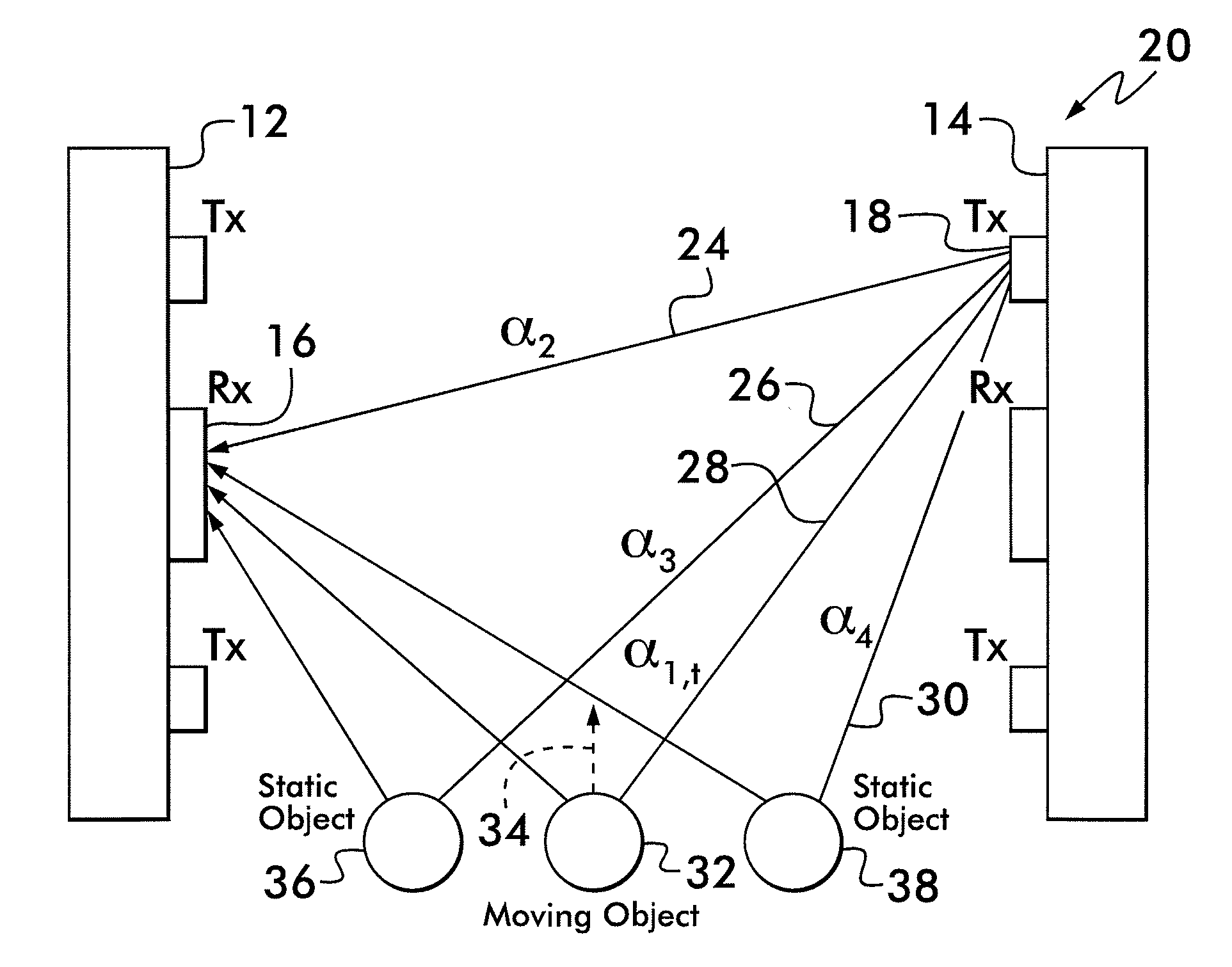
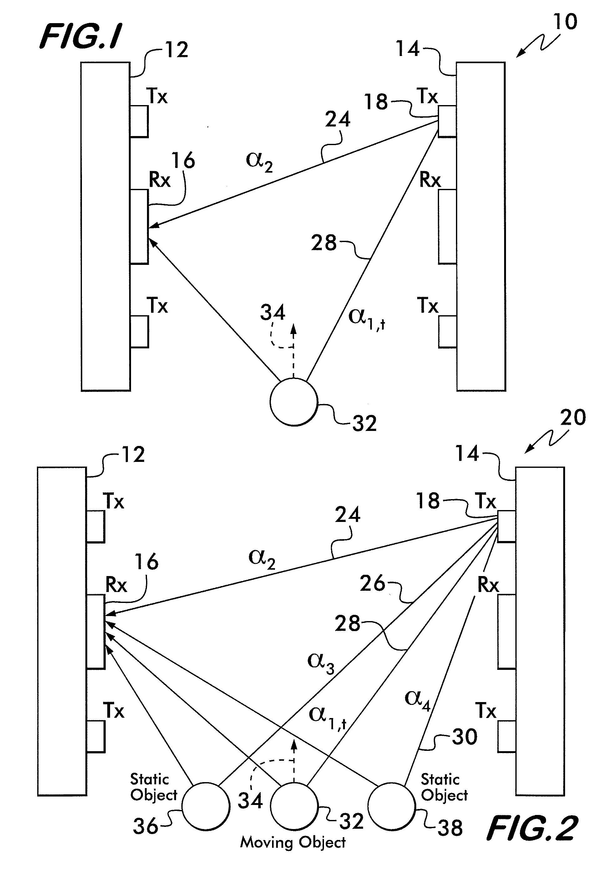
[0031]Referring now to FIG. 1, there is shown a schematic representation of an embodiment of the background object sensing system 10 of the present invention, as viewed looking horizontally into a portal. The background object sensing system 10 includes an RFID receiver 16 mounted on a pedestal 12 and an RFID transmitter 18 mounted on a pedestal 14. The RFID transmitter 18 and RFID receiver 16 can be parts of any known RFID transceiver system. Therefore, while the invention is described with respect to pedestal mounted transmitters and receivers for illustrative purposes, it will be understood that the invention can be practiced using overhead transceiver devices or any other types of transceiver devices. When the RFID transmitter 18 transmits a radio frequency signal it can be received by the RFID receiver 16. For example, the radio frequency signal 24 transmitted from the RFID transmitter 18 can follow the direct line of sight path to the RFID receiver 16. The complex attenuation ...


PUM


Abstract

An RFD reader includes a transceiver configured to receive a first radio frequency signal reflected off at least one surface to provide baseline signal information and a second radio frequency signal reflected off the at least one surface and an object to provide further signal information. A comparator is configured to compare the baseline signal information and the further signal information to provide a signal comparison. A processor is configured to detect the presence of the object in accordance with the signal comparison. A determination is made whether the object is in motion in accordance with the signal comparison. The determination whether the object is in motion is made in accordance with a continuous fluctuation of the second radio frequency signal. A determination whether the object is no longer in motion is made in accordance with an ending of the continuous fluctuation of the second radio frequency signal.

Description

BACKGROUND OF THE INVENTION[0001]1. Field of Invention[0002]The present invention generally relates to the field of RFID communication systems, and more particularly, to a system and method for detecting an object within an RFID communication system.[0003]2. Description of Related Art[0004]In, for example, retail establishments, it is desirable to know whether objects or persons are passing through portals or close to portals being monitored by RFID transceivers. For example, it is desirable to know whether an object or person is present in the region of an entrance or exit of a retail establishment, and whether an object or person is present in the region of any opening or openings between a frontstore and a backstore where inventory is stored. Additionally, it is desirable to know whether an object or person is present in the region of any loading docks, or other types of portals for bringing inventory into or out of the retail establishment. Furthermore, it is desirable to know w...

Claims


Application Information

Patent Timeline
Patent Type & Authority Applications(United States)
IPC IPC(8): G06K7/01
CPCG01S13/56G01S13/58G01S11/10G01S13/92G01S13/876G01S13/003G01S5/14G01S13/878G08B13/248G06K7/10425G01S11/06G06Q10/08
Inventor TKACHENKO, ARTEM
Owner CHECKPOINT SYST INC
Why Eureka
Try Eureka