Illuminating device and display device

a technology which is applied in the field of illumination device and display device, can solve problems such as strength reduction, and achieve the effects of reducing optical loss, improving strength, and reducing the thickness of the illumination devi

Inactive Publication Date: 2012-12-20
SHARP KK
View PDF0 Cites 19 Cited by
  • Summary
  • Abstract
  • Description
  • Claims
  • Application Information

AI Technical Summary

Benefits of technology

[0018]In the illuminating device of the present invention, the light guide plate and the frame are integrally molded by two-color molding. Thus, the strength can be improved compared to the conventional illuminating device obtained by the assembly of the light guide plate and the frame that have been separately produced. Consequently, the illuminating device can be made thinner and lighter.
[0019]On the other hand, at least a part of the end faces of the light guide plate except for the light incident surface is spaced from the frame. Thus, most of the light that has entered from the light guide plate to the portions of the end faces of the light guide plate that are spaced from the frame is totally reflected toward the inside of the light guide plate. Therefore, the optical loss can be reduced, and a reduction in brightness of the illuminating device can be prevented.
[0020]The display device of the present invention includes the above illuminating device, and thus can achieve a small thickness, lightweight, and bright screen while maintaining the necessary strength.

Problems solved by technology

If the thickness and weight of the edge-light type illuminating device are reduced only by reducing the thickness and weight of each component of the illuminating device, a decrease in strength may be a problem.

Method used


Image

  • Illuminating device and display device
  • Illuminating device and display device
  • Illuminating device and display device

Examples


Embodiment Construction

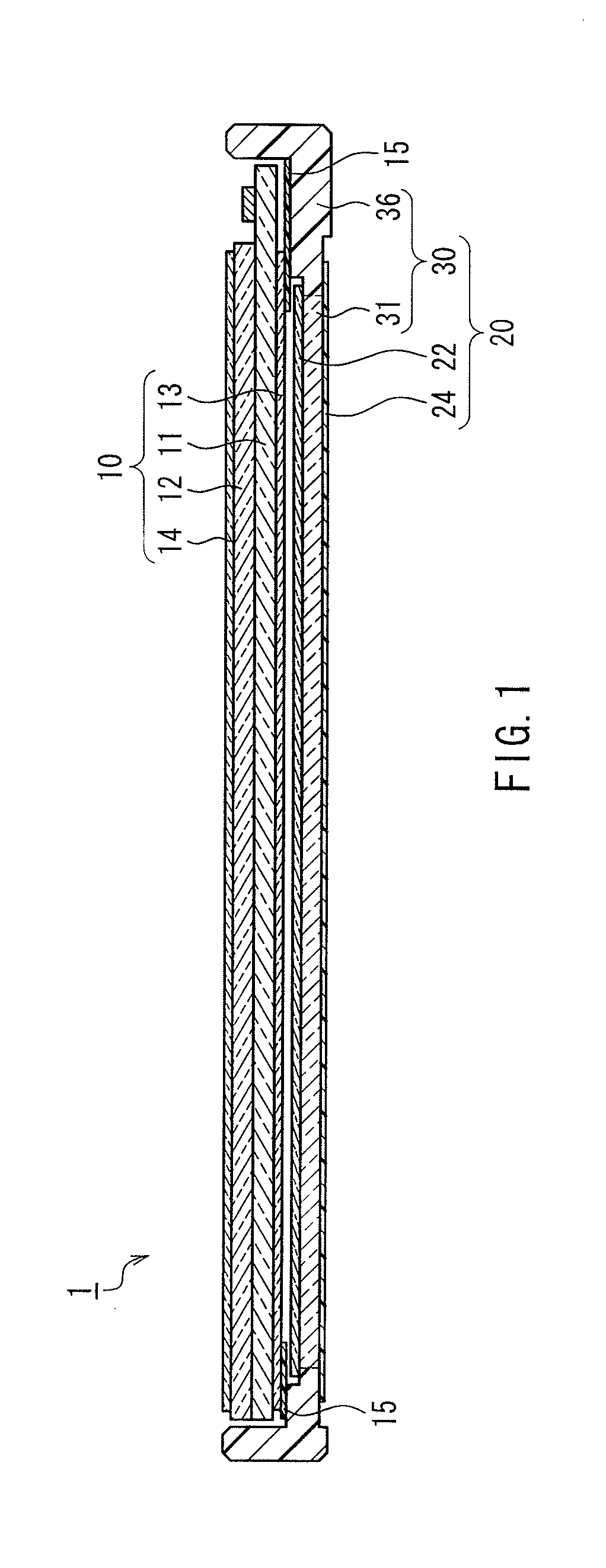
[0028]In the illuminating device of the present invention, the light guide plate and the frame are integrally molded by two-color molding, and at least a part of the end faces of the light guide plate except for the light incident surface is spaced from the frame. The configuration in which the light guide plate and the frame are “spaced” means that they are not in contact with each other. Therefore, as shown in FIG. 6, the configuration in which the light guide plate 140 and the frame 150 are joined in the thickness direction is excluded. Although the end faces of the light guide plate and the frame can be spaced in any portions as desired, it is preferable that those portions are determined in view of non-uniform brightness, strength, or the like of the illuminating device.

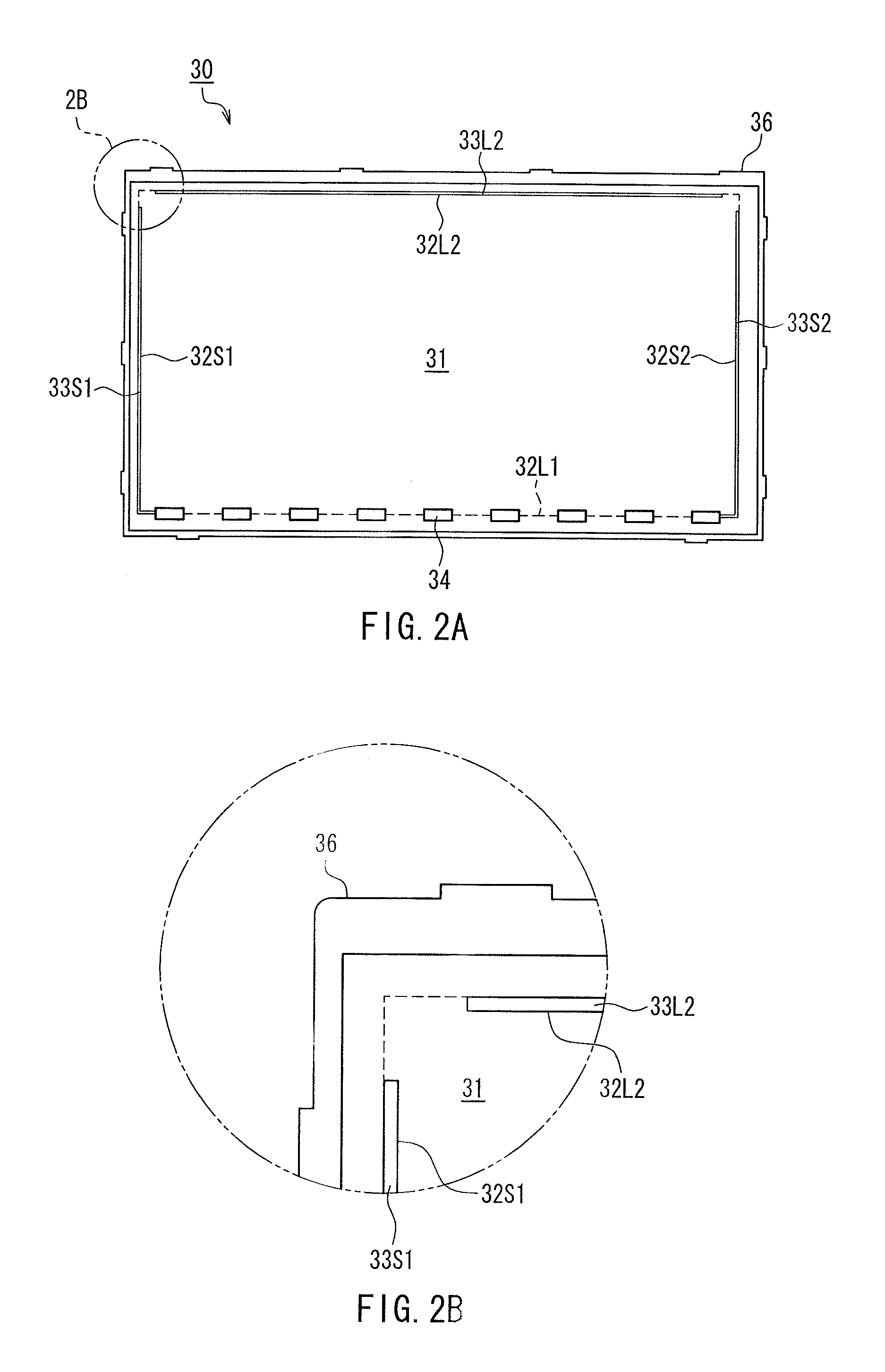
[0029]Specifically, it is preferable that the end faces of the light guide plate except for the light incident surface are joined to the frame in at least one corner portion of four corner portions of the substa...


PUM


Abstract

An illuminating device includes a substantially rectangular light guide plate that includes at least one end face as a light incident surface, a frame that is arranged to surround the light guide plate, and a light source that is located between the light guide plate and the frame so as to face the light incident surface of the light guide plate. The light guide plate and the frame are integrally molded by two-color molding, and at least a part of the end faces of the light guide plate except for the light incident surface is spaced from the frame. Thus, the illuminating device can be made thinner and lighter without reducing the strength and the brightness.

Description

CROSS REFERENCE TO RELATED APPLICATIONS[0001]This application is a national phase of PCT / JP2011 / 058302, filed Mar. 31, 2011 and claims priority to Japanese Application No. 2010-098944, filed Apr. 22, 2010.TECHNICAL FIELD[0002]The present invention relates to an illuminating device, particularly an illuminating device including a light guide plate. The present invention also relates to a display device including the illuminating device.BACKGROUND ART[0003]In recent years, a wide range of liquid crystal display devices has become increasingly thinner and lighter, including not only small liquid crystal display devices used in mobile equipment such as a portable telephone, a notebook computer, a PDA, etc., but also large liquid crystal display devices used in a television etc.[0004]In the liquid crystal display device, an illuminating device (backlight device) is located on the back of a liquid crystal panel, and a user observes light that has been emitted from the illuminating device ...

Claims


Application Information

Patent Timeline
Patent Type & Authority Applications(United States)
IPC IPC(8): F21V7/04F21V8/00
CPCG02B6/0083G02B6/0088G02B6/009H04M1/0266H04M1/22H04W52/027Y02D30/70
Inventor YAMANE, HIROMASAMIWA, MASAHI
Owner SHARP KK
Why Eureka
Try Eureka