
Method for Applying a Metal End to a Container Body

Inactive Publication Date: 2012-12-20
SONOCO DEV INC
View PDF2 Cites 12 Cited by
  • Summary
  • Abstract
  • Description
  • Claims
  • Application Information

AI Technical Summary

Benefits of technology

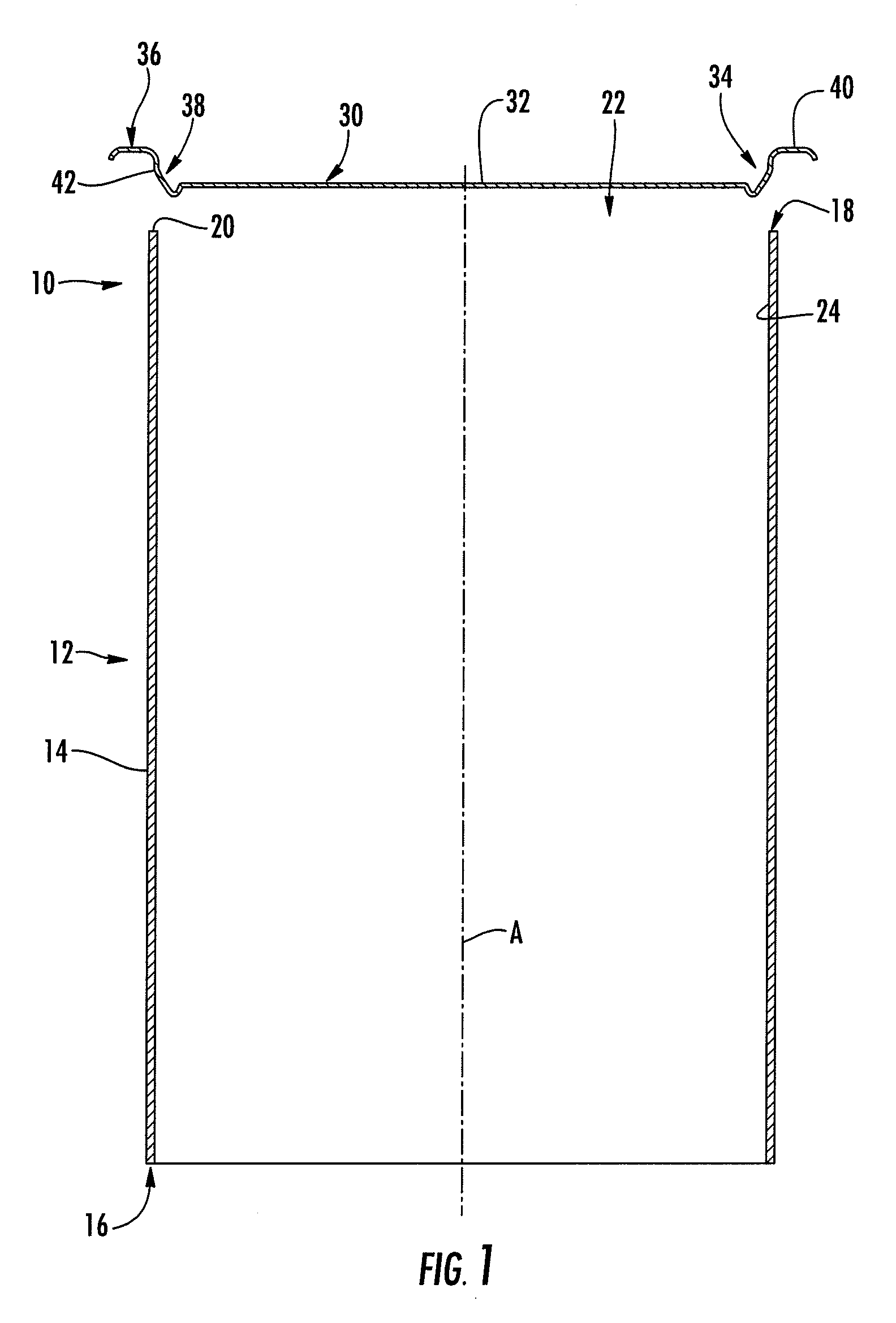
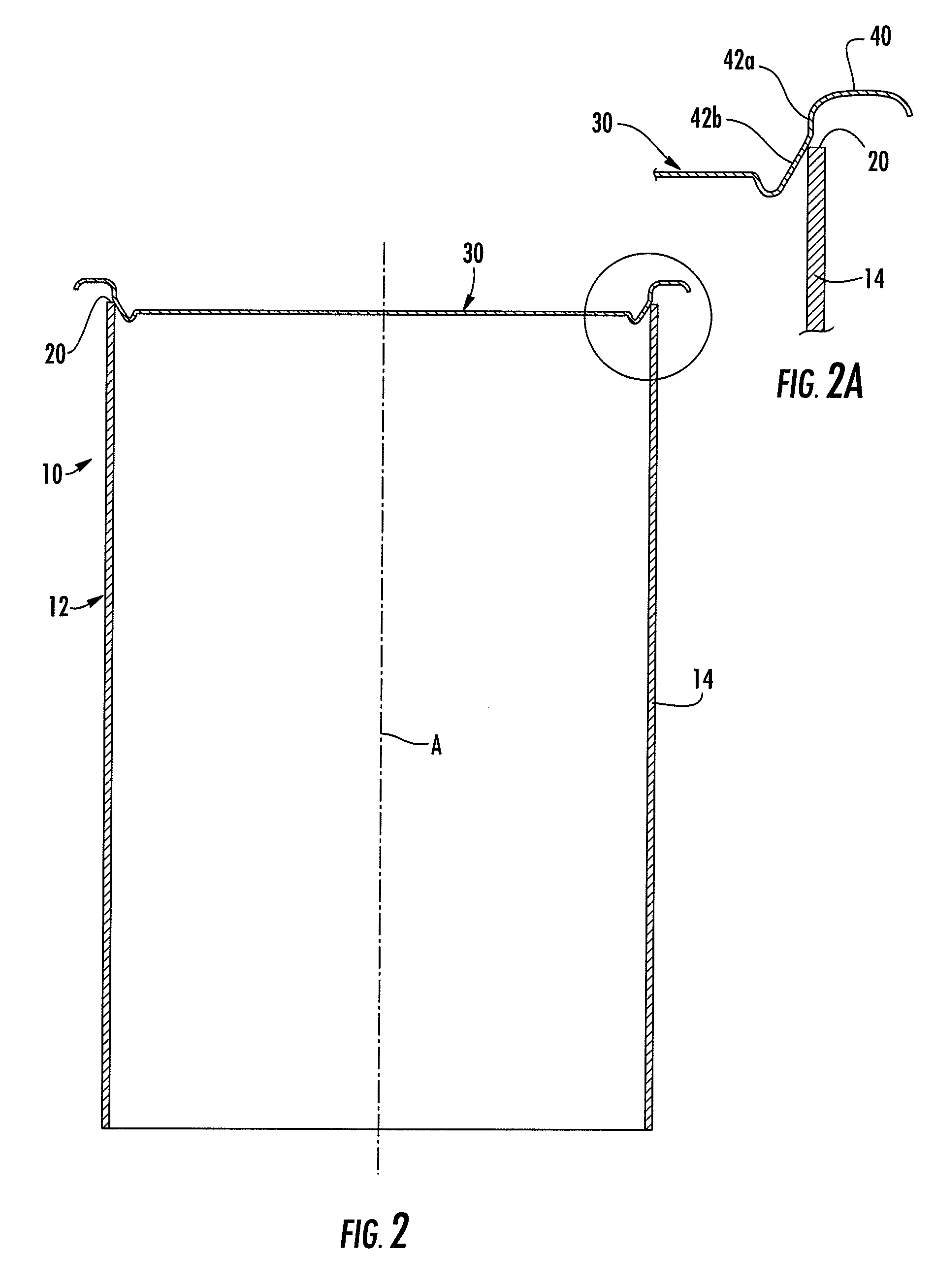
[0011]By providing the compound-angled chuck wall on the metal end, the metal end's application to the container body side wall is facilitated because a substantial diametral clearance can be employed, which helps guide the metal end onto the container body and reduces chances of a misalignment occurring that could cause stoppage of a high-speed automated seaming line. As the side wall proceeds toward the channel, the diametral clearance diminishes and eventually is reduced to zero (or even an interference fit) in order to achieve the tight fit needed between the metal end and the container body for good sealing in the seaming operation.

Problems solved by technology

This makes it considerably more difficult to apply the metal end to the container body in a rapid automated process because even a slight misalignment between the axis of the metal end and the axis of the container body (or an out-of-round condition of the container body) can result in a failed application.
Such a failure is a significant problem in a high-speed automated seaming line.

Method used


Image

  • Method for Applying a Metal End to a Container Body
  • Method for Applying a Metal End to a Container Body
  • Method for Applying a Metal End to a Container Body

Examples


Embodiment Construction

[0030]The present invention now will be described more fully hereinafter with reference to the accompanying drawings in which some but not all embodiments of the inventions are shown. Indeed, these inventions may be embodied in many different forms and should not be construed as limited to the embodiments set forth herein; rather, these embodiments are provided so that this disclosure will satisfy applicable legal requirements. Like numbers refer to like elements throughout.

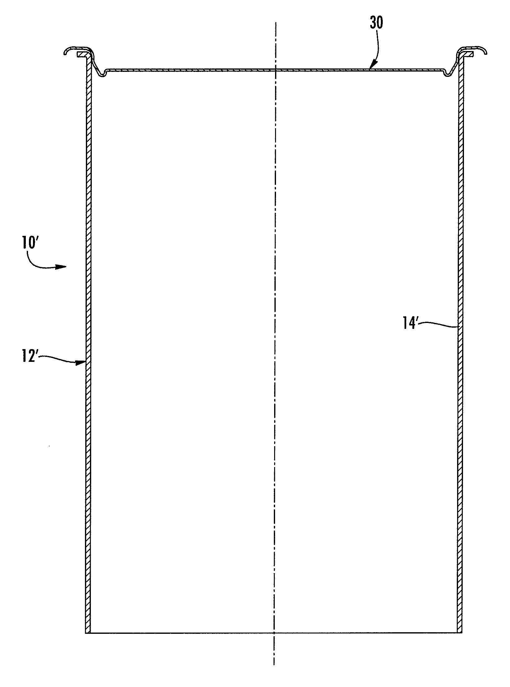
[0031]FIGS. 1 through 5 are a series of sequential views showing steps of a method for applying a closure to a container 10 in accordance with one embodiment of the invention. In these figures, a container body 12 is shown as having a side wall 14 extending about a container body axis A. The side wall has a lower end 16 and an upper end 18. The upper end defines an upper edge 20 that extends about a top opening 22 of the container body 12. The side wall 14 at the upper edge 20 has an inner surface 24 formed by a ...


PUM

PropertyMeasurementUnit
Fractionaaaaaaaaaa
Angleaaaaaaaaaa
Diameteraaaaaaaaaa

Abstract

A metal end is applied and sealed to a plastic or paper / plastic composite container body by a crimp-seaming or double-seaming operation. The metal end has an outer curl joined to a compound-angle chuck wall that extends down from the curl. The chuck wall has an upper part that is substantially linear and at an angle α1 with respect to an axis of the end, and a lower part that is substantially linear and at a larger angle α2 with respect to the axis. The compound-angle chuck wall allows a substantial diametral clearance between a lower end of the lower part of the chuck wall and the inner surface of the container body, while there is substantially zero clearance, or preferably an interference fit, between the upper part of the chuck wall and the inner surface of the container body. Accordingly, the chuck wall guides the end into concentric alignment with the container body during application.

Description

BACKGROUND OF THE INVENTION[0001]The present disclosure relates to containers, particularly to containers having one or two metal ends applied to one or both ends of the container body and crimp-seamed or double-seamed onto the container body, and most particularly to such containers used for retort processing and in which the container body is non-metallic.[0002]Traditionally, retort containers have been constructed substantially entirely of metal. For many decades the standard retort food container has been the metal can, in which a metal can body is closed by a pair of metal ends that are double-seamed onto the ends of the can body. Each metal end has an outer peripheral portion forming a “curl” that receives the end of the can body, and after each end is applied the curl and the end of the can body are rolled up together to form a double seam. This construction has the great advantage that it readily withstands retort processing without the seams being compromised, because the p...

Claims


Application Information

Patent Timeline
IPC IPC(8): B21D51/30B65B7/28
CPCB65B7/28B21D51/2653B21D51/2623B21D51/30
Inventor PRICE, TREVORMORIN, JEREMYDUNN, DAVE
Owner SONOCO DEV INC
Learn More