Automatic Injection Device With Delay Mechanism Including Dual Functioning Biasing Member

a delay mechanism and automatic injection technology, applied in the field of pharmaceutical injection devices, can solve the problems of affecting the operation of the device, affecting the safety of users, so as to reduce the number of injections, ensure the operation, and reduce the profile

Active Publication Date: 2012-12-20
ELI LILLY & CO
View PDF3 Cites 101 Cited by
  • Summary
  • Abstract
  • Description
  • Claims
  • Application Information

AI Technical Summary

Benefits of technology

[0008]One advantage of the present invention is that a delay mechanism may be provided for an automatic injection which allows a timely retraction of the needle without a release from or overcoming of the driving spring of the syringe, and which is not substantially involved with operational forces applied to the syringe during needle insertion and then injection.
[0009]Another advantage of the present invention is that an automatic injection device may be provided with a slim profile.
[0010]Another advantage of the present invention is that an automatic injection device, and such as a delay mechanism therein, may be provided using a reduced number of parts while still having a reliable staging of device operation.

Problems solved by technology

One difficulty with designing an automatic injector with a needle retracting feature is ensuring both that the full desired contents of the syringe have been injected and that the syringe needle is properly retracted into the device housing after use.
While perhaps functional, these solutions are not without their own shortcomings, such as the delay mechanism being used to transfer force to the syringe during injection.
Further, the number of parts, and the camming motion of the delay mechanism with parts sliding against each other, complicates assembly and operation.
Automatic injectors frequently are provided with a lock feature that frustrates device triggering prior to a user having prepared for such triggering.
Various means to prevent this plunger unlatching from occurring too soon have been employed in the past, but such means are not without their shortcomings, such as due to increasing the device complexity or adding undesirable size to the device.

Method used


Image

  • Automatic Injection Device With Delay Mechanism Including Dual Functioning Biasing Member
  • Automatic Injection Device With Delay Mechanism Including Dual Functioning Biasing Member
  • Automatic Injection Device With Delay Mechanism Including Dual Functioning Biasing Member

Examples


Embodiment Construction

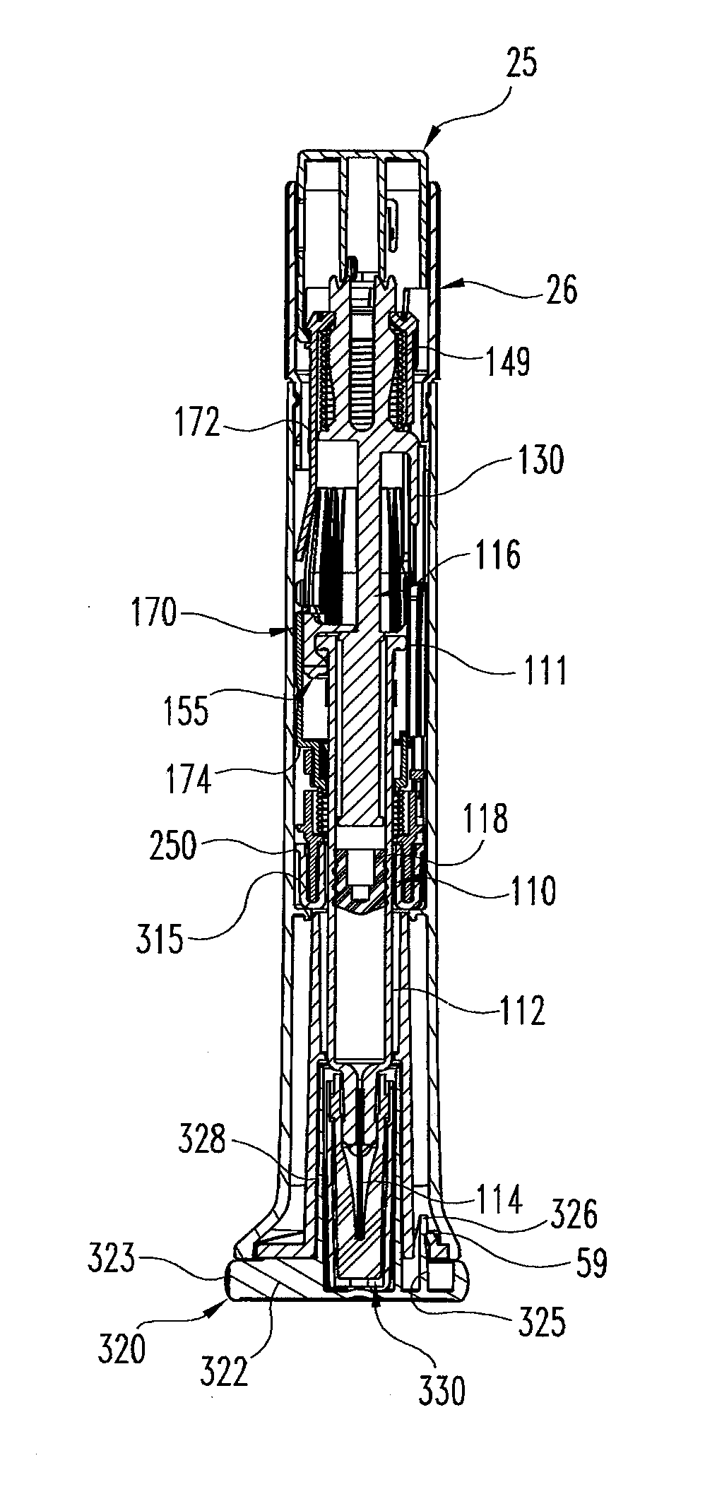
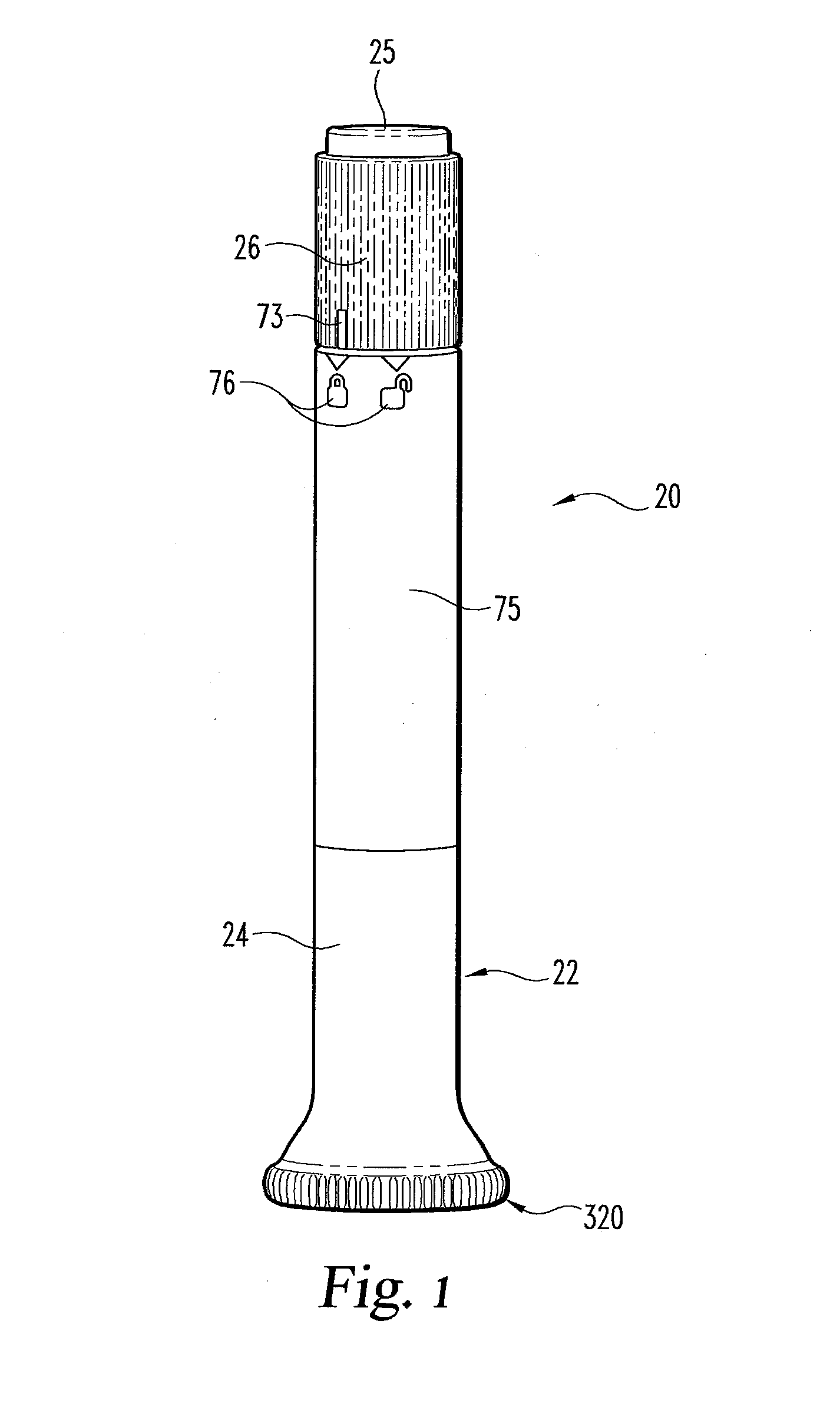
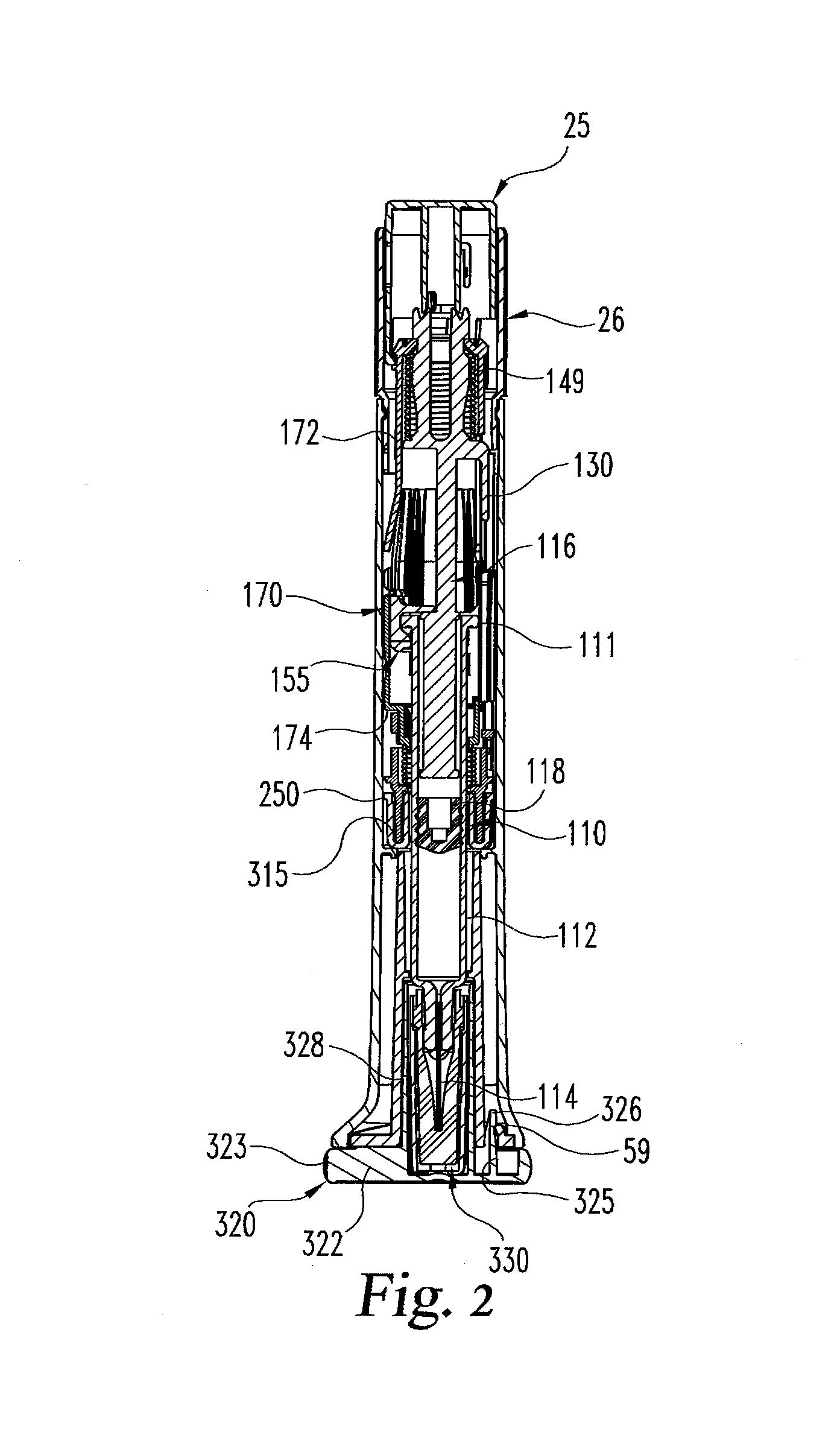
[0028]Referring now to FIGS. 1 and 2, there are shown different views of a first embodiment of an automatic injection apparatus with a delay mechanism of the present invention.

[0029]The automatic injection apparatus, generally designated 20, has a trigger that when actuated by a user results in the needled syringe of the apparatus automatically being driven downward such that the injection needle projects beyond the bottom end of the apparatus housing to penetrate the user. The apparatus then proceeds to inject automatically the medication contents of the syringe through the needle, after which the syringe is retracted automatically such that the injection needle is returned to within the housing. The delay mechanism of the apparatus helps to stage the operation to ensure that the medication contents are properly delivered prior to the needled syringe being retracted.

[0030]It will be appreciated from the following description that apparatus 20 is conceptually similar in various aspe...


PUM


Abstract

An automatic injection apparatus including a delay mechanism for properly delivering medication prior to the needled syringe of the apparatus being retracted. In one form, the delay mechanism includes a shuttle (170) for the syringe, a follower (250), a locking member, a damping compound between the follower and a supporting surface (308) to dampen rotation of the follower relative to the shuttle, and a dual functioning biasing member (290) acting between the shuttle and the follower. When the locking member moves to a release position during an injection, the dual functioning biasing member first provides a torsional force to force the follower to rotate relative to the shuttle from a latching position to an unlatching position, and then the dual functioning biasing member provides an axial force to force the shuttle axially relative to the follower to move the shuttle for retracting the syringe needle into the housing of the apparatus after injection.

Description

BACKGROUND OF THE INVENTION[0001]The present invention pertains to pharmaceutical injection devices, and, in particular, to an automatic injection device.[0002]Patients suffering from a number of different diseases frequently must inject themselves with pharmaceuticals. A variety of devices have been proposed to facilitate these injections. One type of device is an automatic injection device. This type of device, when triggered by a user, automatically inserts into the user a needle of a syringe that prior to triggering was disposed within the device housing, and then automatically injects a dose of medication through that inserted needle. One known type of automatic injection device then automatically advances a shroud to cover the needle when the dose is completed. In another type of automatic injection device having a configuration more desirable to some, and instead of having an advancing shroud, the device will automatically retract the needle into the housing when the dose is ...

Claims


Application Information

Patent Timeline
Patent Type & Authority Applications(United States)
IPC IPC(8): A61M5/315A61M5/20
CPCA61M2005/2073A61M2005/3143A61M2005/3247A61M5/3204A61M5/2033A61M5/326A61M2005/206A61M2205/583A61M5/20
Inventor ADAMS, MATTHEW ROBERTFOURT, JESSE ARNOLDKAPLAN, JONATHAN I.SILBERSCHATZ, PAUL JOSEPHYURCHENCO, JAMES R.
Owner ELI LILLY & CO
Why Eureka
Try Eureka