
Automated assembly apparatus and method of assembling components by using automated assembly apparatus

a technology of automatic assembly and assembly apparatus, which is applied in the direction of process and machine control, program control, instruments, etc., can solve the problems of difficult to detect the completion of angle matching

Inactive Publication Date: 2012-12-27
CANON KK
View PDF10 Cites 14 Cited by
  • Summary
  • Abstract
  • Description
  • Claims
  • Application Information

AI Technical Summary

Benefits of technology

[0022]The present invention provides a method of assembling components that have to be subjected to angle matching by accurately detecting completion of angle matching of the components regardless of the length of time from when angle matching is complete to when insertion is complete during an automated assembly of the components. The present invention also provides an automated assembly apparatus.

Problems solved by technology

It is therefore difficult to detect the completion of performing angle matching with the technologies known in the art in the case, for example, where signals from a force sensor are received every 2 ms, or in the case of assembling small components or performing high-speed assembly such that the insertion is complete in a time that is shorter than the interval at which the signals are received.
Thus, it has been difficult to detect the completion of performing angle matching by using the change in the pressing force Fz.

Method used


Image

  • Automated assembly apparatus and method of assembling components by using automated assembly apparatus
  • Automated assembly apparatus and method of assembling components by using automated assembly apparatus
  • Automated assembly apparatus and method of assembling components by using automated assembly apparatus

Examples


Embodiment Construction

[0039]Referring to the drawings, an embodiment of the present invention will be described below.

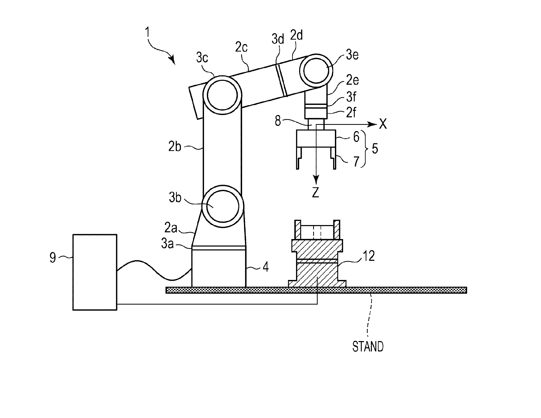
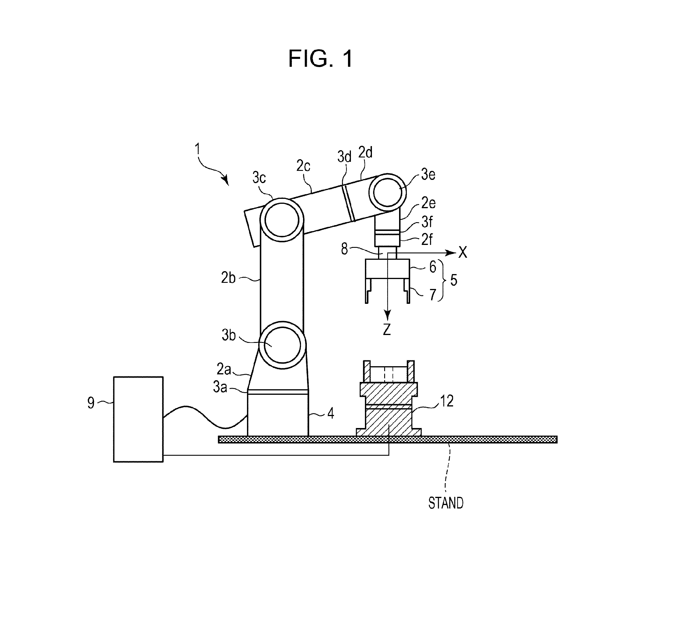
[0040]FIG. 1 is a front view of an apparatus that performs assembly with an automated component-assembly method according to an embodiment of the present invention and schematically illustrates a basic configuration of the apparatus.

[0041]As illustrated in FIG. 1, the apparatus that performs assembly with an automated component-assembly method according to the embodiment includes a robot 1 and a grasping mechanism 5. By using the robot 1 and the grasping mechanism 5, the apparatus is capable of grasping a component to be assembled, transporting the component, and assembling the component and another component together.

[0042]The robot 1 includes multiple actuators and linkages and has six degrees of freedom. Specifically, first to sixth linkages 2a, 2b, 2c, 2d, 2e, and 2f are connected to each other via rotatable or swivelable first to sixth joints 3a, 3b, 3c, 3d, 3e, and 3f and are driven...


PUM

PropertyMeasurementUnit
Forceaaaaaaaaaa

Abstract

While a second component is brought into contact with a first component, the first component and the second component are rotated with respect to each other around a specific rotation axis, and rotation of the first component and the second component is stopped when a moment created around the rotation axis exceeds a predetermined threshold.

Description

BACKGROUND OF THE INVENTION[0001]1. Field of the Invention[0002]The present invention relates to an automated assembly apparatus that assembles components using a robot and also relates to a method of assembling components by using the automated assembly apparatus.[0003]2. Description of the Related Art[0004]FIGS. 10 and 11 illustrate an automated assembly apparatus disclosed in Japanese Patent No. 03288518 and FIGS. 12A and 12B illustrate a typical force sensor. FIG. 10 illustrates a basic configuration of the automated assembly apparatus when seen from the front. FIG. 11 is a schematic diagram of components that are to be assembled together, one of the components being placed on a positioning mechanism, the other being fed by a component feeding mechanism.[0005]As illustrated in FIG. 10, the automated assembly apparatus includes a robot 21 and a grasping mechanism 20. The robot 21 is a type of robot that is generally called a “Selective Compliance Assembly Robot Arm” or SCARA. The...

Claims


Application Information

Patent Timeline
IPC IPC(8): B23P19/04B23P11/00
CPCB23P19/105B25J9/1687G05B2219/40032Y10T29/5303Y10T29/4978Y10T29/49776Y10S901/34
Inventor YAMAMOTO, YUYA
Owner CANON KK
Learn More