Shock absorber
a technology of shock absorber and shock absorber, which is applied in the direction of shock absorber, vibration damper, spring/damper, etc., can solve the problems of shock absorber not being able to control the damping force characteristics in response, deterioration of driving comfort, and inability to ensure vehicle stability, etc., to reduce the damping force
- Summary
- Abstract
- Description
- Claims
- Application Information
AI Technical Summary
Benefits of technology
Problems solved by technology
Method used
Image
Examples
first embodiment
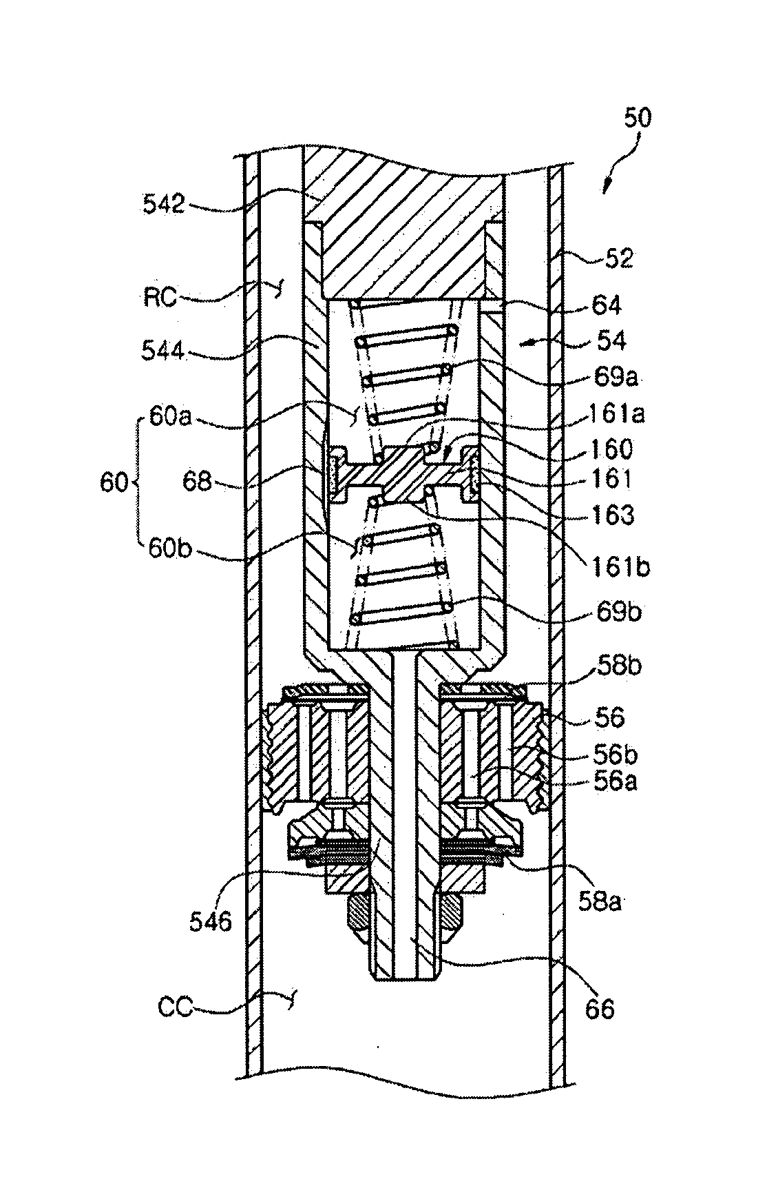
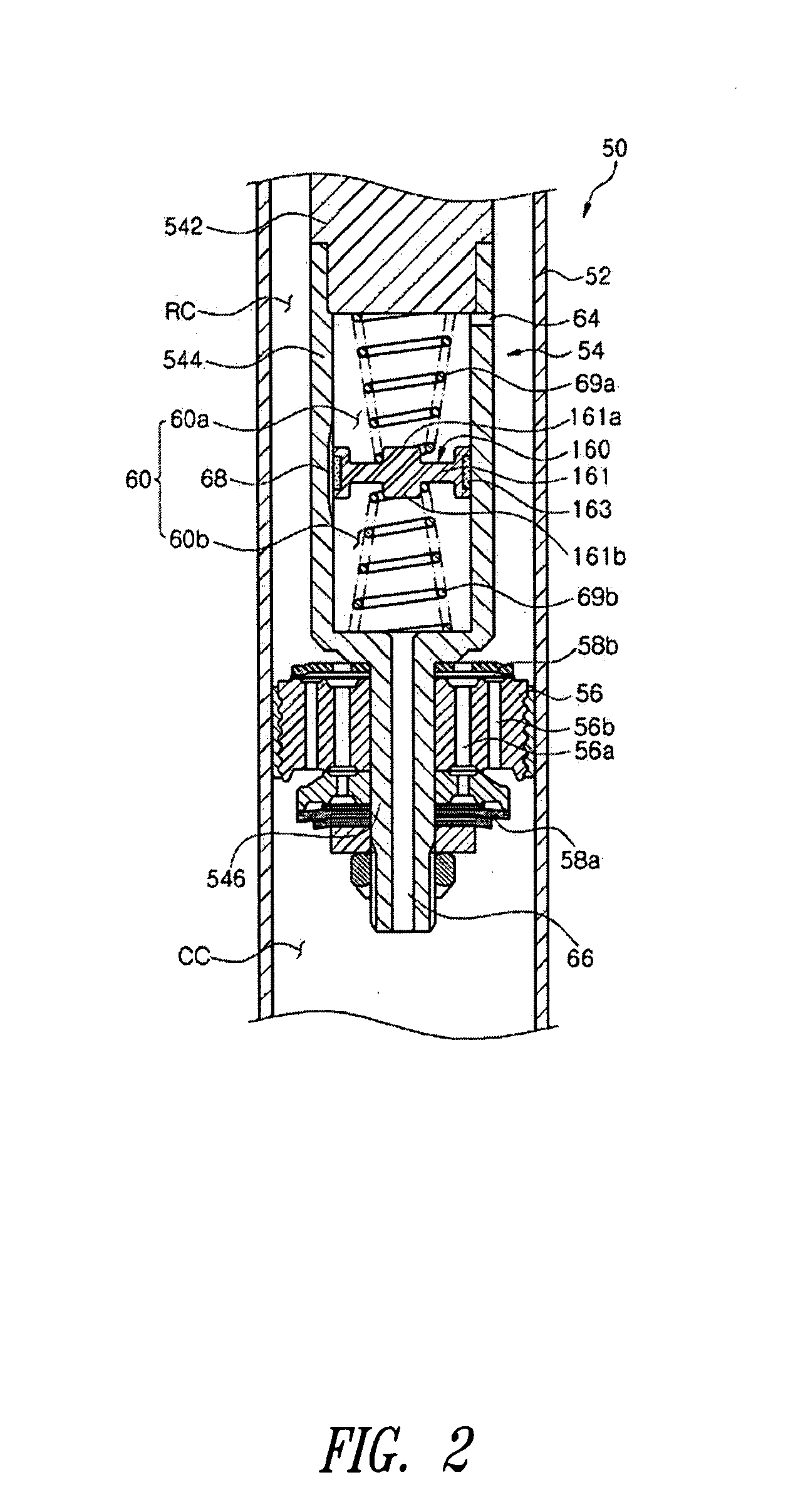
[0049]In this manner, the shock absorber 50 generates a very low damping force while the operating fluid is bypassed from one chamber to the other chamber through the groove 68.
[0050]Referring to FIG. 4 showing operation of the shock absorber 50 to generate a low damping force, a relatively large displacement of the piston rod 54 causes the floating piston 160 to move between an outer region of the section L1 having the bypass passage defined by the groove 68 and the maximum range of motion L2 of the floating piston 160.
[0051]In this case, a resilient force is generated by the upper and lower springs 69a and 69b to rapidly move the floating piston 160.
[0052]That is, when the piston rod 54 of the shock absorber 50 is relatively largely displaced, the floating piston 160 is moved between L1 and L2. Further, in the tensile stroke of the piston rod 54, that is, when the piston rod 54 is raised, the floating piston 160 is rapidly moved downward by a restoration force of the upper spring...
second embodiment
[0071]In this manner, when the piston rod 54 is minutely moved, the shock absorber 51 generates a very low damping force while the operating fluid is moved within the hollow chamber 60 by deformation of the flexible moving plate 264.
[0072]Referring to FIG. 8 showing operation of the shock absorber 51 to generate a low damping force, a relatively large displacement of the piston rod 54 causes the floating piston 260 to move between an outer region of the section L1 and the maximum range L2 of motion of the floating piston 260 while the flexible moving plate 264 is deformed at the same time.
[0073]Further, in the tensile stroke of the piston rod 54, that is, when the piston rod 54 is raised, the floating piston 260 is lowered while the flexible moving plate 264 is deformed downward at the same time. Accordingly, the operating fluid in the tensile chamber RC is supplied to the upper chamber 60a, while the operating fluid in the lower chamber 60b is discharged to the compression chamber...
PUM
 Abstract
Description
Claims
Application Information
 - R&D
- Intellectual Property
- Life Sciences
- Materials
- Tech Scout
- Unparalleled Data Quality
- Higher Quality Content
- 60% Fewer Hallucinations
Browse by: Latest US Patents, China's latest patents, Technical Efficacy Thesaurus, Application Domain, Technology Topic, Popular Technical Reports.
© 2025 PatSnap. All rights reserved.Legal|Privacy policy|Modern Slavery Act Transparency Statement|Sitemap|About US| Contact US: help@patsnap.com


