Vibration damping bushing and manufacturing method thereof

a technology of vibration damping bushing and manufacturing method, which is applied in the direction of shock absorbers, manufacturing tools, transportation and packaging, etc., can solve the problems of insufficient inability to achieve the targeted running stability of the vehicle or the durability of the main rubber elastic body, and difficulty in ensuring enough resistance force to prevent the stopper member from slipping out in the axial direction. , to achieve the effect of avoiding structural complications, increasing the number of manufacturing processes,

Active Publication Date: 2012-12-27
HONDA MOTOR CO LTD +1
View PDF8 Cites 7 Cited by
  • Summary
  • Abstract
  • Description
  • Claims
  • Application Information

AI Technical Summary

Benefits of technology

[0024]According to the seventh mode, when the tapered surface of the cylindrical jig is abutted against the latching piece in the axial direction, displacement of the stopper member from a targeted mounting position on the inner axial member caused by pressing pressure exerted on the latching piece (stopper member) by the cylindrical jig can be prevented. Therefore, the stopper member is mounted to the right position on the inner axial member to exert a targeted stopper effect and a vibration damping effect.
[0025]Moreover, the positioning of the stopper member relative to the inner axial member is realized by the positioning mechanism using the step portion of the inner axial member, which renders any special component or jig for positioning unnecessary. Therefore, it is possible to avoid structural complications or an increase in the number of manufacturing processes due to the increase in the number of components, thus enabling to simplify the operation without any need for a setup operation to a jig and the like.
[0026]According to the present invention, the slipping out prevention mechanism is configured by having the latching piece engaged with the latching depression in the axial direction, and the displacement of the stopper member from the inner axial member toward the slipping out side in the axial direction is prevented. Therefore, the stopper effect is effectively exerted by the abutment of the stopper member against the outer cylindrical member, thus achieving improvements in durability and running stability by means of limiting relative displacement between the inner axial member and the outer cylindrical member.

Problems solved by technology

However, since the stopper member constituting the first stopper mechanism is fitted into the inner axial member only by pressing, it is difficult to secure enough resistance force to prevent the stopper member from slipping out in the axial direction.
Therefore, if the stopper member is hit hard by the mounting cylinder of the suspension arm due to an input of a shockingly large load, the stopper member may possibly be displaced off the inner axial member to the other side in the axial direction, thus creating a risk that the stopper effect in the axial direction by the first stopper mechanism would not be exerted stably.
As a result, there were some occasions when targeted running stability of the vehicle or durability of the main rubber elastic body could not be obtained sufficiently.

Method used


Image

  • Vibration damping bushing and manufacturing method thereof
  • Vibration damping bushing and manufacturing method thereof
  • Vibration damping bushing and manufacturing method thereof

Examples


Embodiment Construction

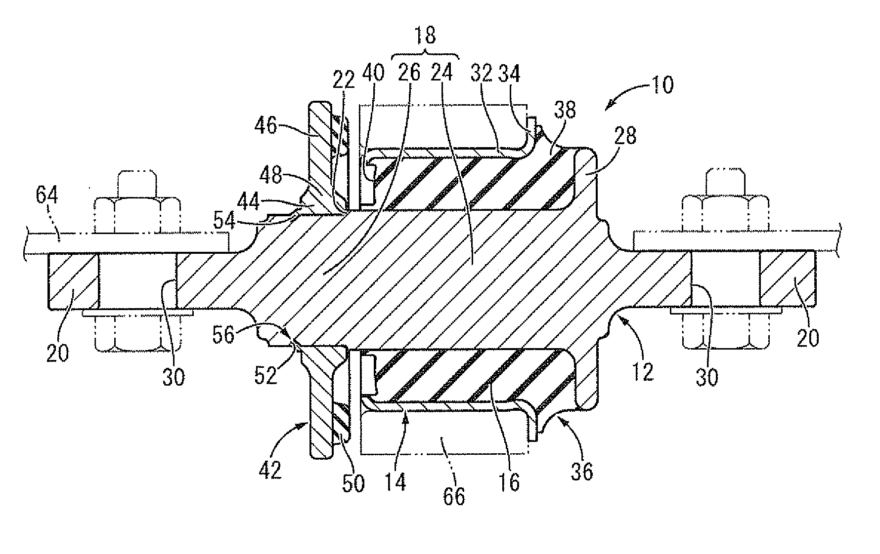
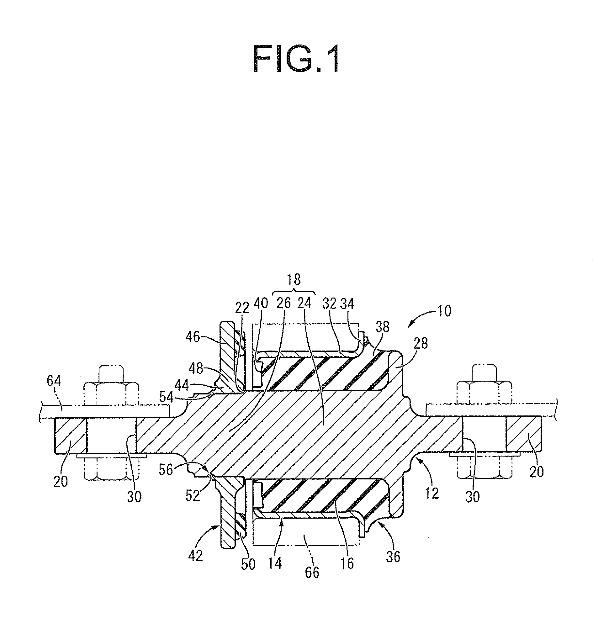
[0033]FIG. 1 shows a suspension bushing 10 for a motor vehicle as an embodiment of the vibration damping bushing with the structure according to the present invention. The suspension bushing 10 has a structure wherein an inner axial member 12 is inserted through an outer cylindrical member 14, while these inner axial member 12 and outer cylindrical member 14 are elastically connected with each other by a main rubber elastic body 16. In the following descriptions, the axial direction generally means the left-right direction in FIG. 1. In FIG. 1, the suspension bushing 10 is indicated by solid lines whereas a vehicular body 64 (including bolts and nuts for mounting) and a mounting cylinder 66, which will be described later, are indicated by two-dotted lines.

[0034]More specifically, the inner axial member 12 is a high-rigidity member made of metal materials such as iron and aluminum alloy and the like and is integrally provided with a central main body 18 in an approximate form of a cy...


PUM

PropertyMeasurementUnit
vibration dampingaaaaaaaaaa
relative displacementaaaaaaaaaa
elasticaaaaaaaaaa

Abstract

A vibration damping bushing including: an inner axial member; an outer cylindrical member through which the inner axial member is inserted; a main rubber elastic body elastically connecting the two members; and a stopper member that is fitted onto the inner axial member as a component of a first stopper mechanism that limits relative displacement of the inner axial member against the outer cylindrical member to one side in an axial direction. The inner axial member is formed with a latching depression that opens toward an outer periphery thereof, and the stopper member is provided with a latching piece that protrudes outward in the axial direction. The latching piece is engaged with the latching depression so as to provide a slipping out prevention mechanism for preventing the stopper member from slipping out from the inner axial member.

Description

INCORPORATED BY REFERENCE[0001]The disclosure of Japanese Patent Application No. 2011-137161 filed on Jun. 21, 2011 including the specification, drawings and abstract is incorporated herein by reference in its entirety.BACKGROUND OF THE INVENTION[0002]1. Field of the Invention[0003]The present invention relates to a vibration damping bushing used for vibration damping connection, for example, between a suspension arm and a vehicular body in an automobile suspension mechanism. The present invention also relates to a method for manufacturing the same.[0004]2. Description of the Related Art[0005]Conventionally, in an automobile suspension mechanism and the like, a vibration damping bushing has been disposed at a connecting portion between a suspension arm that supports wheels and a vehicular body, and the suspension arm and the vehicular body are connected in a vibration damping fashion via the vibration damping bushing. One example of the vibration damping bushing is disclosed in Unex...

Claims


Application Information

Patent Timeline
Patent Type & Authority Applications(United States)
IPC IPC(8): F16F7/00B23P11/00
CPCB60G7/001B60G2204/41Y10T29/49844F16F1/3863F16F1/3828
Inventor MAKINO, TAKASHITANAKA, CHIHARUKOBAYASHI, AKIRA
Owner HONDA MOTOR CO LTD
Why Eureka
Try Eureka