Light emitter driving device and lighting appliance therewith

a technology of driving device and light emitter, which is applied in the direction of electric variable regulation, process and machine control, instruments, etc., can solve the problems of over-the-top trouble, difficult to completely remove the flicker from the led, etc., and achieve the effect of preventing the flicker of the light emitter

Inactive Publication Date: 2012-12-27
ROHM CO LTD
View PDF5 Cites 73 Cited by
  • Summary
  • Abstract
  • Description
  • Claims
  • Application Information

AI Technical Summary

Benefits of technology

[0012]In light of the above problems found by the inventors of the present application, it is an object of the present invention to provide a light emitter driving device that is able to prevent a flicker of a light emitter due to malfunction of a TRIAC dimmer and a lighting appliance that uses the light emitter driving device.

Problems solved by technology

Besides, for example, as shown in FIG. 11C, in a case where a frequency trouble occurs in the output waveform from the TRIAC dimmer, the LED repeats unintentional on / off, whereby a flicker occurs. FIG. 11B and FIG. 11C each exemplifies an overview in which the above trouble suddenly occurs during a period T; however, there is also a risk that the above trouble could occur constantly over a plurality of the periods T.
Here, in the conventional LED driver IC, as a measure against the malfunction of the TRIAC dimmer, a bleeder circuit for keeping the hold current of the TRIAC dimmer and an RC filter for applying a filter process to the output waveform from the TRIAC dimmer and the like are externally connected; however, it is hard to completely remove the flicker from the LED.

Method used


Image

  • Light emitter driving device and lighting appliance therewith
  • Light emitter driving device and lighting appliance therewith
  • Light emitter driving device and lighting appliance therewith

Examples


Embodiment Construction

LED LIGHTING APPLIANCE

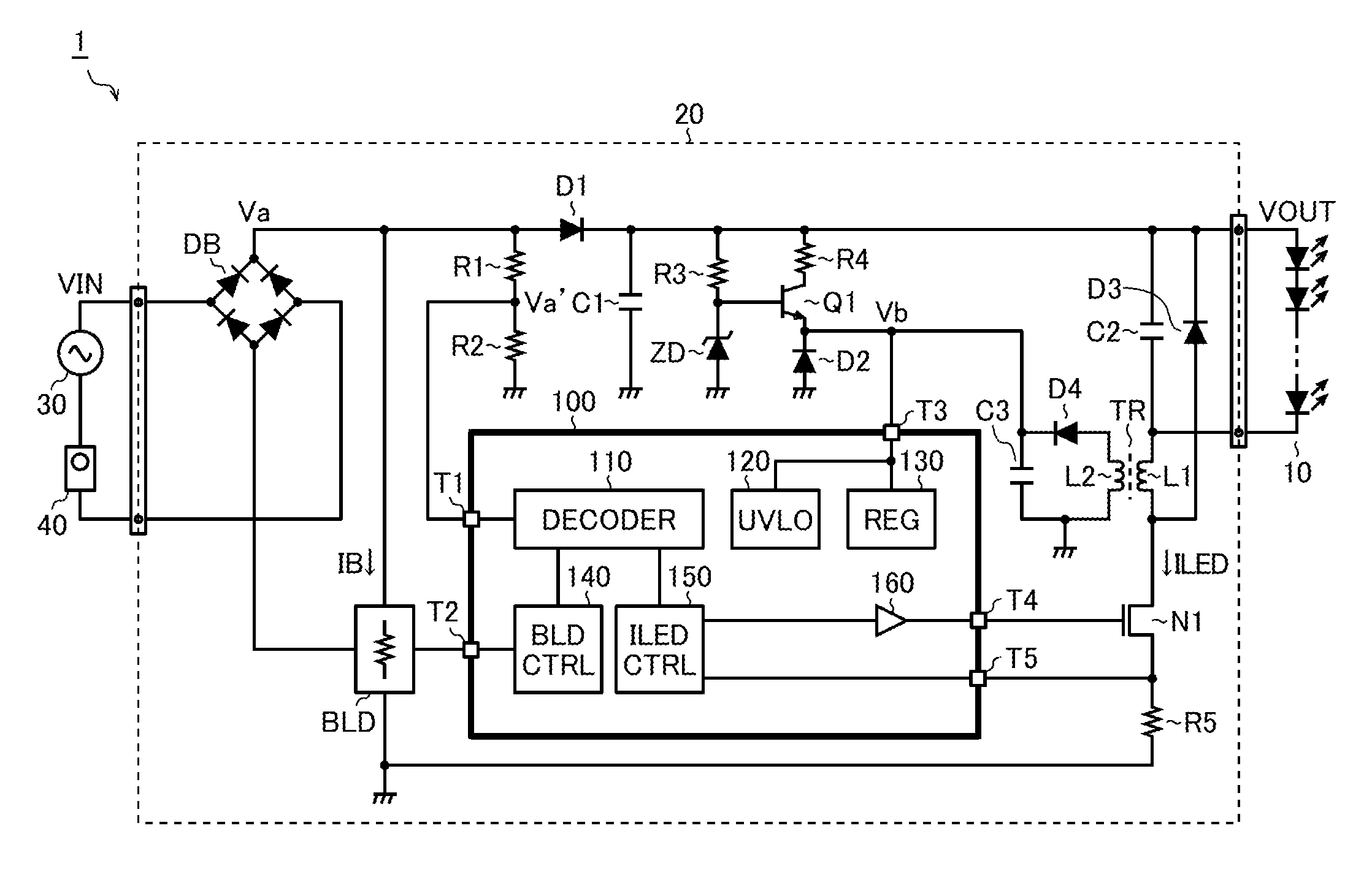
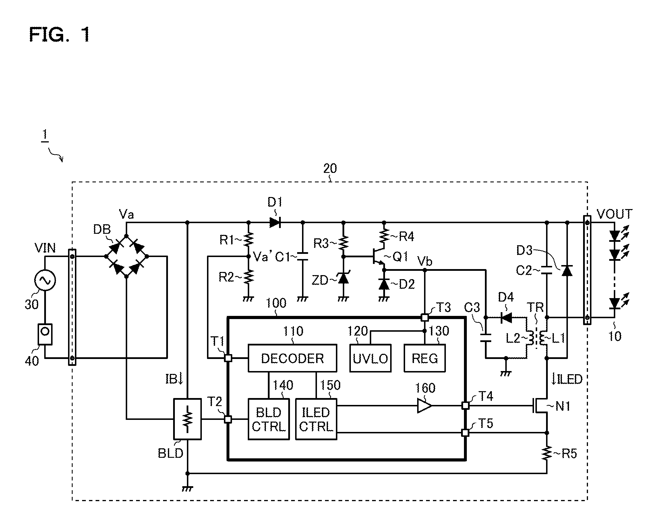
[0030]FIG. 1 is a diagram showing a structural example of an LED lighting appliance. An LED lighting appliance 1 in the present structural example has an LED module 10 and a power supply module 20.

[0031]The LED module 10 is a light source of the LED lighting appliance 1 that emits light which has a daylight color (a color temperature of about 5000 K) or a warm white color (a color temperature of about 3000 K), and includes a plurality of LED devices that are connected in series or in parallel.

[0032]The power supply module 20 converts an a.c. voltage VIN supplied from a commercial a.c. power supply 30 (e.g., 90 to 220 VAC) into a d.c. voltage VOUT (e.g., 50 VDC) and supplies it to the LED module 10. The power supply module 20 includes an LED driver IC 100 and various discrete components (a diode bridge DB, a bleeder circuit BLD, resistors R1 to R5, diodes D1 to D4, a Zener diode ZD, capacitors C1 to C3, an npn type bipolar transistor Q1, an N channel type MOS fi...


PUM


Abstract

A light emitter driving device has a decoder portion which monitors a rectified voltage and generates a dimming signal, and a drive current control portion which controls a drive current to a light emitter according to the dimming signal. The decoder portion has a comparator which compares the rectified voltage with a predetermined threshold voltage to generate a comparison signal, a sampling counter which measures high-level and low-level periods of the comparison signal, a duty calculation portion which calculates the duty of the rectified voltage based on the output of the sampling counter, a filter calculation portion which excludes sporadic variation in duty by applying digital filtering to the output of the duty calculation portion, and a dimming signal generation portion which generates the dimming signal based on the output of the filter calculation portion.

Description

CROSS-REFERENCE TO RELATED APPLICATIONS[0001]This application is based on the following Japanese Patent Applications, and the contents of which are hereby incorporated by reference:[0002](1) Japanese Patent Application No. 2011-139207 (the filing date: Jun. 23, 2011)[0003](2) Japanese Patent Application No. 2012-117438 (the filing date: May 23, 2012)BACKGROUND OF THE INVENTION[0004]1. Field of the Invention[0005]The present invention relates to a light emitter driving device that drives a light emitter such as an LED (light emitting diode) and the like, and to a lighting appliance that uses the light emitter driving device.[0006]2. Description of Related Art[0007]In recent years, various LED driver ICs compatible with a TRIAC (bidirectional thyristor) dimming method are put in practical applications. The TRIAC dimming method is a dimming method that has been conventionally employed as a dimming method for an incandescent lamp and the like. Accordingly, if an LED driver IC compatible...

Claims


Application Information

Patent Timeline
Patent Type & Authority Applications(United States)
IPC IPC(8): H05B37/00H05B44/00
CPCH05B33/0815H05B33/0824H05B33/0851H05B37/02Y02B20/383H05B33/08Y02B20/347H05B45/10H05B45/44Y02B20/30H05B44/00
Inventor SUMITANI, TAKESHISAWADA, AKINOBU
Owner ROHM CO LTD
Why Eureka
Try Eureka