
Wireless battery charger of moving coil type

a technology of moving coils and wireless batteries, which is applied in the direction of electric vehicles, transportation and packaging, electric power, etc., can solve the problems of high price of devices, guide formation of round metal bars, and high cost of devices

Inactive Publication Date: 2012-12-27
TANASHIN DENKI CO
View PDF3 Cites 32 Cited by
  • Summary
  • Abstract
  • Description
  • Claims
  • Application Information

AI Technical Summary

Benefits of technology

[0018]an X-axis slider that can move freely in the X-axis direction;
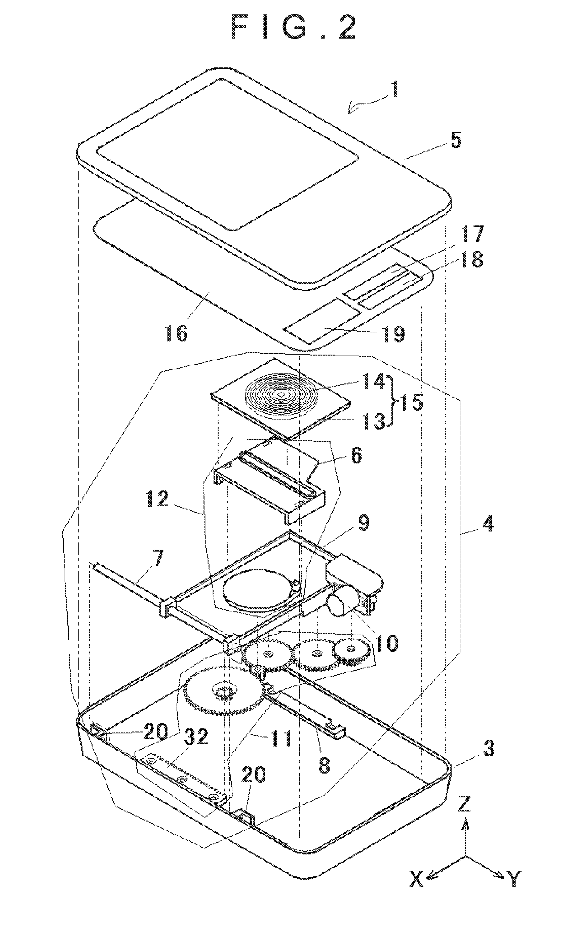
[0031]Therefore, although the table with the transmitter coil can move freely both in the X-axis direction and in the Y-axis direction, motors and metal guides are not required to be equipped respectively for each axis direction. A structure of the device can be simplified by using only one motor and only one metal guide for one of the axis directions. In addition, the device can be cheaper by reducing a number of the expensive motors and metal guides to be used.

Problems solved by technology

In addition, the guides (6, 9) are formed from a round metal bar and very expensive.
Because the expensive components should be adopted for the X-axis direction and the Y-axis direction respectively, a device becomes expensive.

Method used


Image

  • Wireless battery charger of moving coil type
  • Wireless battery charger of moving coil type
  • Wireless battery charger of moving coil type

Examples


Embodiment Construction

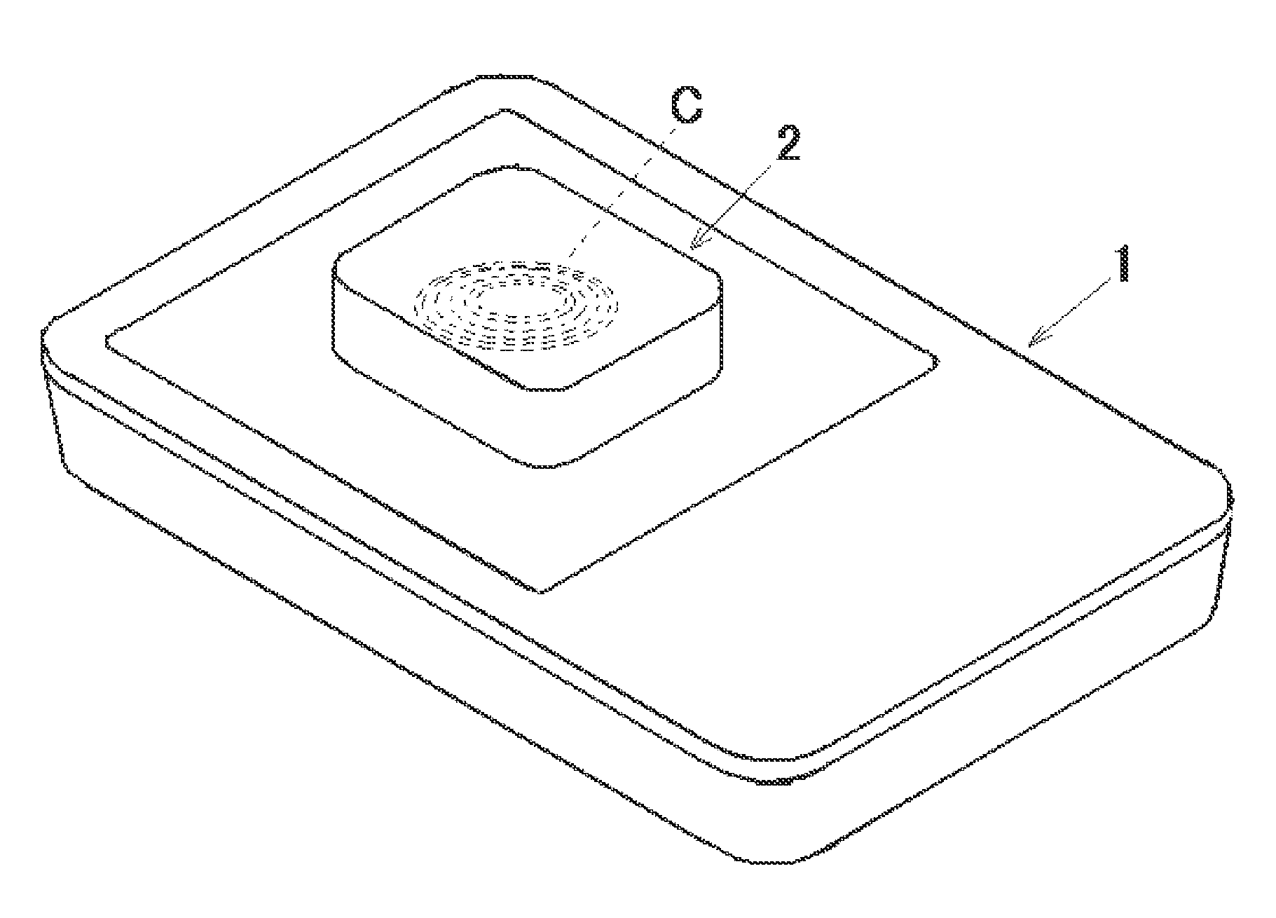
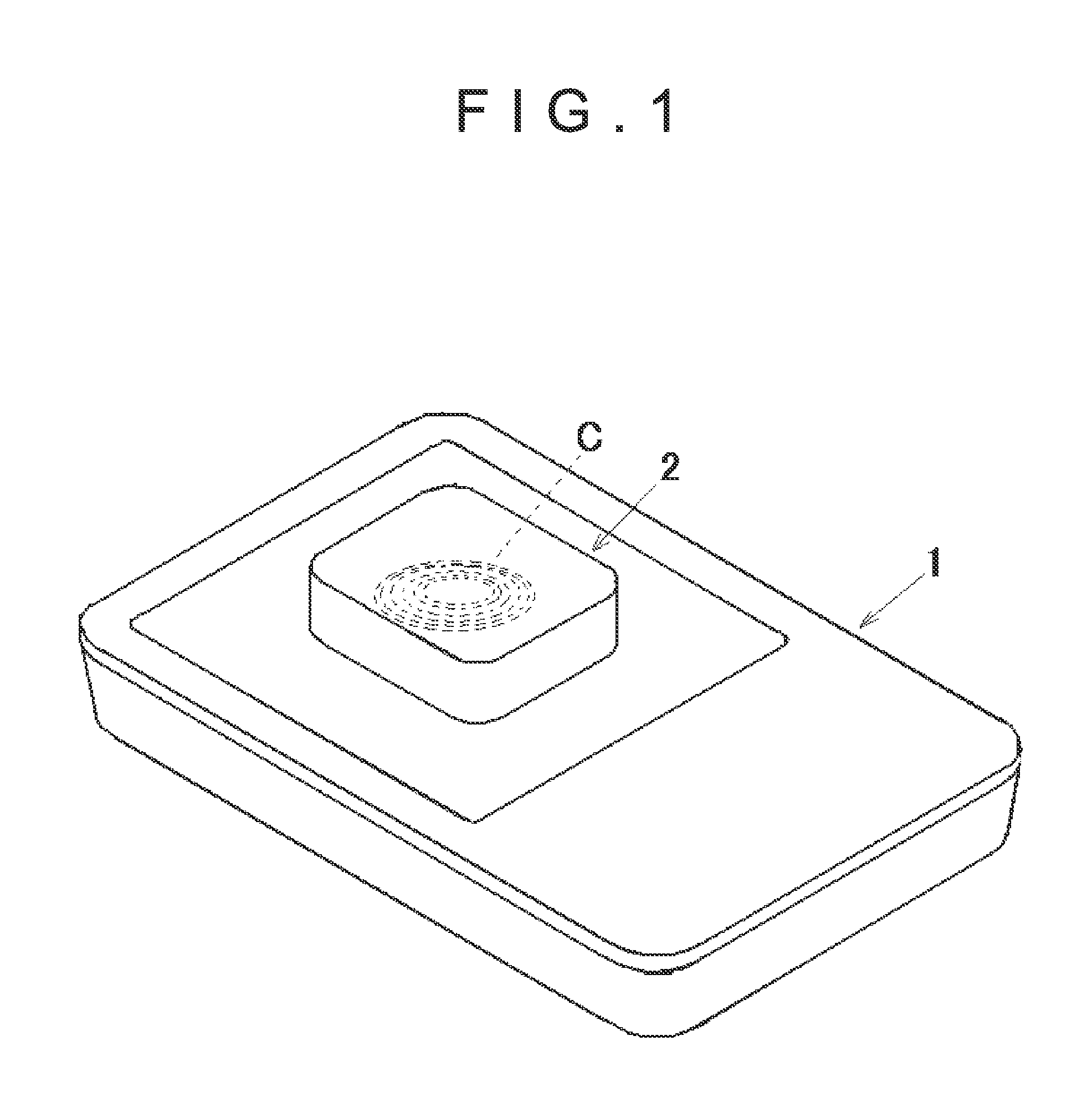
[0058]A preferred embodiment of the present invention will be described below with reference to figures. FIG. 1 is a perspective view of a wireless battery charger 1 of moving coil type and a rechargeable battery 2 that includes a receiver coil C of an electronic device concerning the present invention.

[0059]The wireless battery charger 1 can transfer electrical power from the wireless battery charger 1 to the rechargeable battery 2 to charge the rechargeable battery 2 only by placing the rechargeable battery 2 on an upper side of the wireless battery charger 1 without connecting them by a connector or the like. Various methods can be used to transfer the electrical power from the wireless battery charger to the rechargeable battery. In the embodiments of the present invention, coils are installed on the battery charger side (transmitter side) and the rechargeable battery side (receiver side) respectively, and the electrical power of the battery charger is transferred to the recharg...


PUM


Abstract

The present invention discloses a wireless battery charger of moving coil type that moves a table (15) that mounts a transmitter coil (14) freely in an X-axis direction and in a Y-axis direction having a fixing guide (21), an X-axis slider (6) a Y-axis slider (9), a motor (10), a power transfer means (11) that transfers power of the motor to one of the X-axis slider or the Y-axis slider, a power distribution part (12) that distributes the power of the motor transferred to one slider to another slider, and the table (15) that mounts the transmitter coil (14) wherein the transmitter coil mounted on the table can move freely by transferring the power of the motor to both the one slider and the another slider. Therefore a structure of the battery charger can be simplified, the battery charger can be cheaper and electrical efficiency can be improved.

Description

CROSS-REFERENCES TO RELATED APPLICATIONS[0001]The present application is related to the Japanese Patent Application No. 2011-136942, filed Jun. 21, 2011, the entire disclosure of which is expressly incorporated by reference herein.BACKGROUND OF THE INVENTION[0002]1. Field of the Invention:[0003]This invention relates to a wireless battery charger of moving coil type.[0004]2. Description of the Related Art:[0005]It is known that a wireless battery charger of moving coil type that detects a receiver coil included in a rechargeable battery when the rechargeable battery is placed on the battery charger, moves a table that mounts a transmitter coil freely in an X-axis direction and a Y-axis direction toward the receiver coil, and transfers electrical power from the transmitter coil to the receiver coil.[0006]Various techniques are proposed for the wireless battery charger of moving coil type that enables the table with the transmitter coil to move freely in the X-axis direction and the Y...

Claims


Application Information

Patent Timeline
IPC IPC(8): H02J7/00
CPCH02J7/025H02J7/0044H02J50/005H02J50/90H02J50/10
Inventor SHUKUYA, REI
Owner TANASHIN DENKI CO
Learn More