Advanced remote nondestructive inspection system and process

a non-destructive inspection and advanced technology, applied in wave based measurement systems, instruments, reradiation, etc., can solve the problem that methods do not provide desired measurement precision for accurate analysis of test results

Active Publication Date: 2012-12-27
THE BOEING CO
View PDF4 Cites 42 Cited by
  • Summary
  • Abstract
  • Description
  • Claims
  • Application Information

AI Technical Summary

Problems solved by technology

These methods do not provide desired measurement precision for accurate analysis of test results.

Method used


Image

  • Advanced remote nondestructive inspection system and process
  • Advanced remote nondestructive inspection system and process
  • Advanced remote nondestructive inspection system and process

Examples


Embodiment Construction

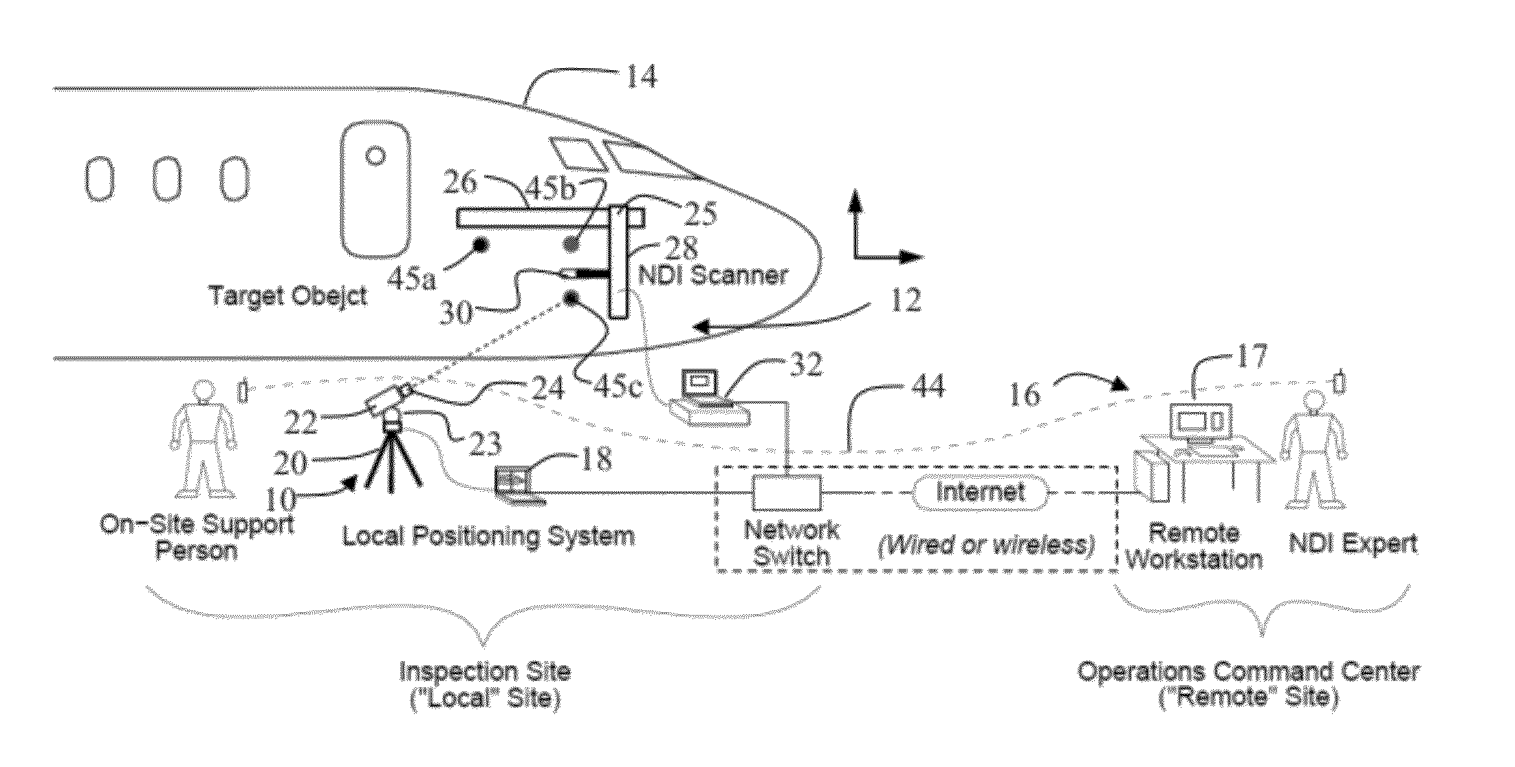
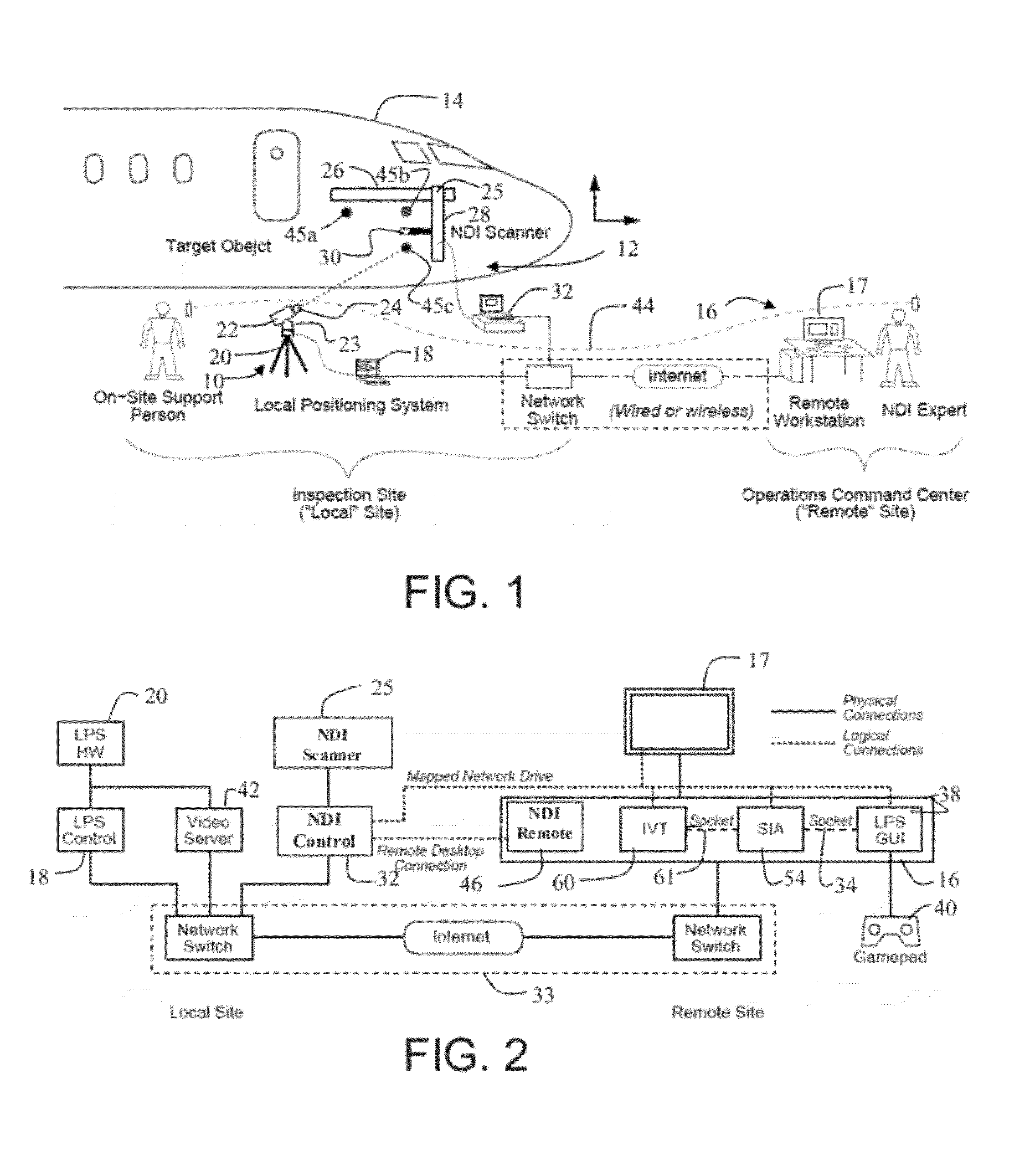
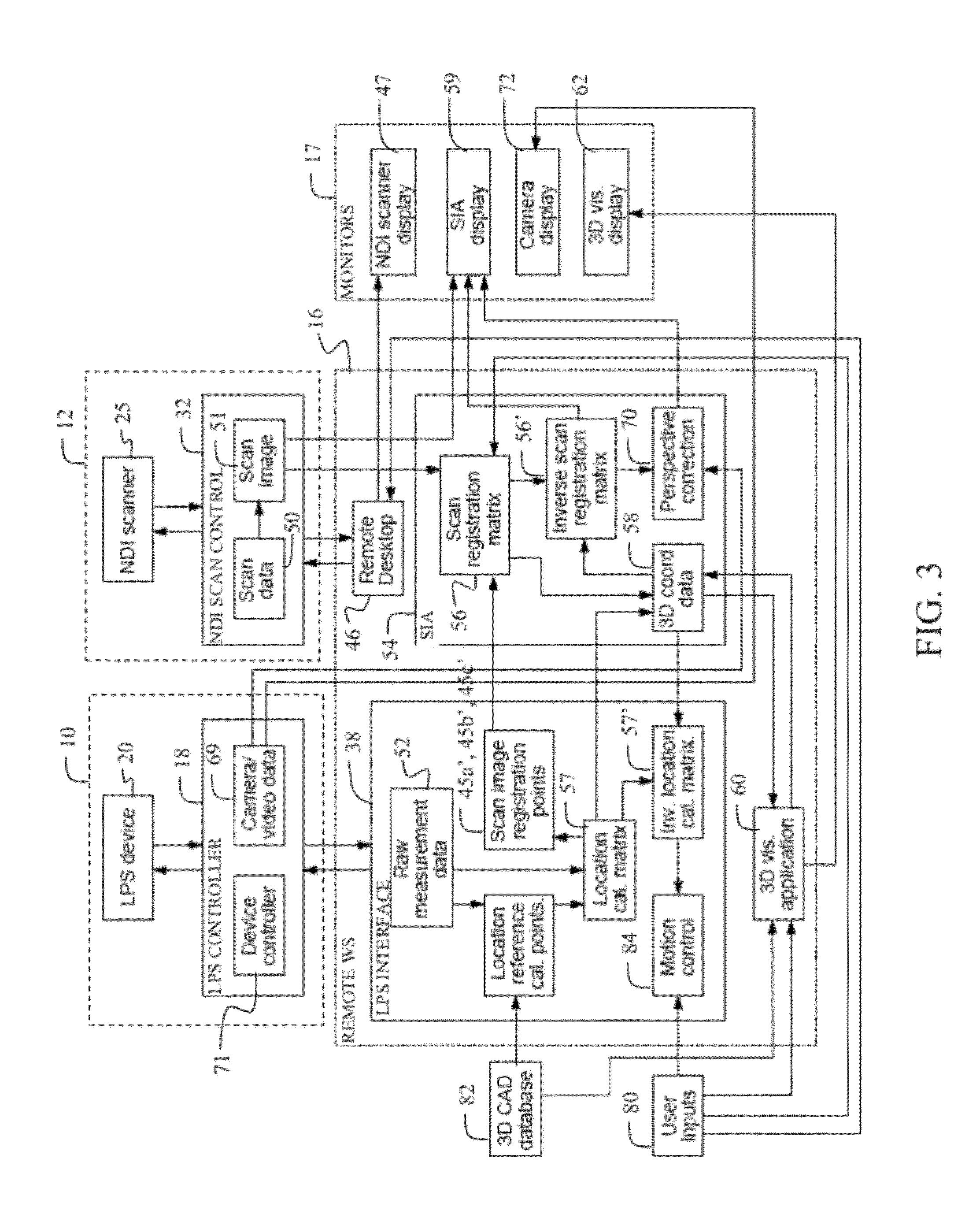
[0018]The embodiments described herein provide a remote acquisition and analysis system for non-destructive inspection (NDI) employing multiple hardware and software components networked through a central analysis interface. The integration of these components enables a remote operator to acquire and analyze NDI data using automated scanning equipment and a local positioning system (LPS), and then visualize and interact with the data in 2D and 3D analysis software. Alignment points measured by the LPS in the scanning area are used to create a positional correspondence for setup of the scanning equipment and registering the resulting 2D scan data in the coordinate system of a 3D CAD model visualization environment.

[0019]The ability to operate all of the hardware and software components remotely enables data collection by an expert NDI analyst from an off-site operations center, with the only on-site assistance coming from non-expert support personnel to setup the LPS and NDI scanning...


PUM


Abstract

A system for inspecting a test article incorporates a diagnostic imaging system for a test article. A command controller receives two dimensional (2D) images from the diagnostic imaging system. A three dimensional (3D) computer aided design (CAD) model visualization system and an alignment system for determining local 3D coordinates are connected to the command controller. Computer software modules incorporated in the command controller are employed, in aligning, the 2D images and 3D CAD model responsive to the local 3D coordinates. The 2D images and 3D CAD model are displayed with reciprocal registration. The alignment system is then directed to selected coordinates in the 2D images or 3D CAD model.

Description

REFERENCE TO RELATED APPLICATIONS[0001]This application is copending with application Ser. No. 11 / 555,953 entitled REMOTE NONDESTRUCTIVE INSPECTION SYSTEMS AND METHODS filed on Ser. No. 11 / 02 / 2006 by Jeffrey R. Kollgaard, Gary E. Georgeson, Blake A. Bertrand, and Richard H. Bossi, application Ser. No. 11 / 863,755 entitled LOCAL POSITIONING SYSTEM AND METHOD filed on Sep. 28, 2007 by Scott W. Lea, Gary E. Georgeson, James J. Troy, M. Matsen, J. Hansen and C. Richards, application Ser. No. 12 / 897,408 entitled METHODS AND SYSTEMS FOR LOCATING VISIBLE DIFFERENCES ON AN OBJECT filed on Oct. 4, 2010 by James J. Troy and Scott W. Lea, application Ser. No. 13 / 036,619 entitled DISTRIBUTED OPERATION OF A LOCAL POSITIONING SYSTEM filed on Feb. 28, 2011 by James J. Troy and Scott W. Lea, which have a common assignee with the present application and which are incorporated herein by reference as though fully set forth.BACKGROUND INFORMATION[0002]1. Field[0003]Embodiments of the disclosure relate g...

Claims


Application Information

Patent Timeline
Patent Type & Authority Applications(United States)
IPC IPC(8): H04N13/02
CPCG01N29/0654G01S15/8938G01S17/88G01N29/4472G01N29/262G01N29/30G01N29/043
Inventor TROY, JAMES J.LEA, SCOTT W.GEORGESON, GARY E.MOTZER, WILLIAM P.HELLENBRAND, PETER J.PUTERBAUGH, KEVIN
Owner THE BOEING CO
Why Eureka
Try Eureka