
Animated image vision test

a technology of vision test and animate image, which is applied in the field of vision testing devices and methods, can solve the problems of inability to accurately test vision and acuity, and waste of tim

Active Publication Date: 2012-12-27
HYTOWITZ ALLAN N
View PDF1 Cites 15 Cited by
  • Summary
  • Abstract
  • Description
  • Claims
  • Application Information

AI Technical Summary

Benefits of technology

[0008]In various exemplary embodiments, the technology described herein provides a device, system, and associated method for more accurately testing vision and acuity related to the correctness of prescriptions for eyeglasses and contact lenses.
[0011]In yet another exemplary embodiment, the technology described herein provides a vision test system for more accurately testing vision and acuity related to the correctness of prescriptions for eyeglasses and contact lenses. The vision test system includes a plurality of interchangeable animated dynamic optotype image shapes, each shape adapted for use to measure the visual acuity of a subject, wherein each of the plurality of interchangeable animated dynamic optotype images comprises a rotating image. Each of the plurality of interchangeable animated dynamic optotype images can be scaled in size in such a way as to compare directly to the distance and acuity scale of Snellen and Landolt “C” vision tests on a visual display. A viewing distance and a refraction of the each of the plurality of interchangeable animated dynamic optotype images can be varied to test vision. Each of the plurality of interchangeable animated dynamic optotype images can be scaled in size in such a way as to compare directly to the distance and acuity scale of a Landolt “C” vision test and Snellen vision test on a visual display.
[0024]Advantageously, the technology described herein provides an improved method for more accurately and more rapidly perceiving visual acuity. Also advantageously, the technology described herein provides an improved vision test chart.

Problems solved by technology

A disadvantage of the Snellen type static images is that even defocused letters can still be partially recognized by their blur patterns.
Much time is thus wasted as the patient, whose eyes are being tested, attempts to guess the letter.
The design of the Snellen chart is further complicated by each letter having a different degree of recognizability and by the tendency of the patient to strain to perceive coherency when trying to identify the letters.
These factors create a potential for both over-refraction and over-compensation.
Numerous other studies have shown difficulties with generating appropriate projected Snellen images as based upon technology developed in 1922 and updated in 1948.
Projection systems are typically dependent upon a darkened room to enhance the contrast of the Snellen images, thereby creating a “contrast sensitivity” which may compromise actual acuity.
Projection systems also inherently create a “fuzzy” image resulting from the mechanics of the diffraction of light waves, thus decreasing the accuracy and precision of the perceived refraction.
Such displays eliminate the inherent fuzziness of the Snellen test, but they still do not eliminate the tendency to misperceive letters and images inherent in focusing on significantly distant static images.

Method used


Image

  • Animated image vision test
  • Animated image vision test
  • Animated image vision test

Examples


Embodiment Construction

[0046]Before describing the disclosed embodiments of this technology in detail, it is to be understood that the technology is not limited in its application to the details of the particular arrangement shown here since the technology described is capable of other embodiments. Also, the terminology used herein is for the purpose of description and not of limitation.

[0047]In various exemplary embodiments, the technology described herein provides a device, system, and associated method for more accurately testing vision and acuity related to the correctness of prescriptions for eyeglasses and contact lenses.

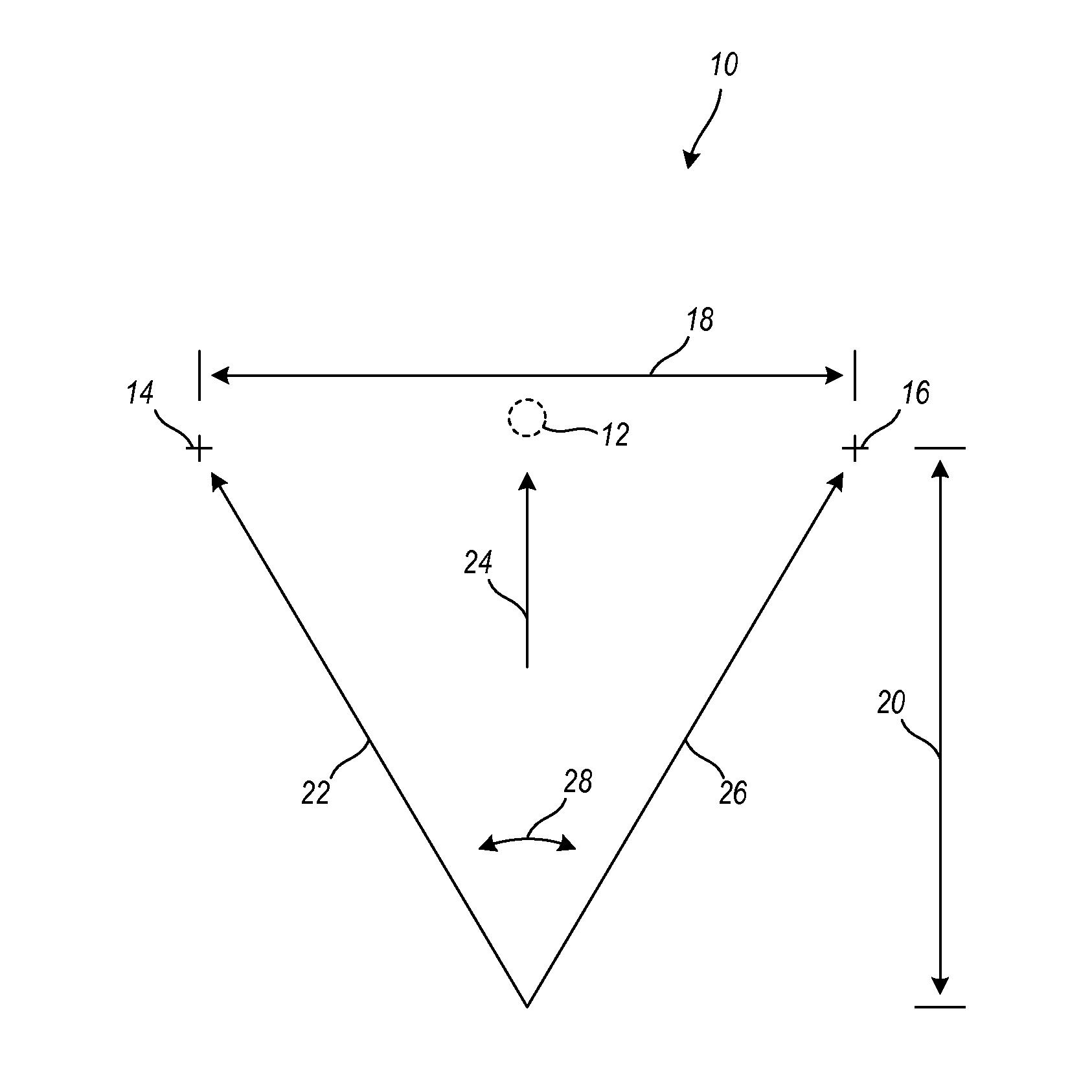
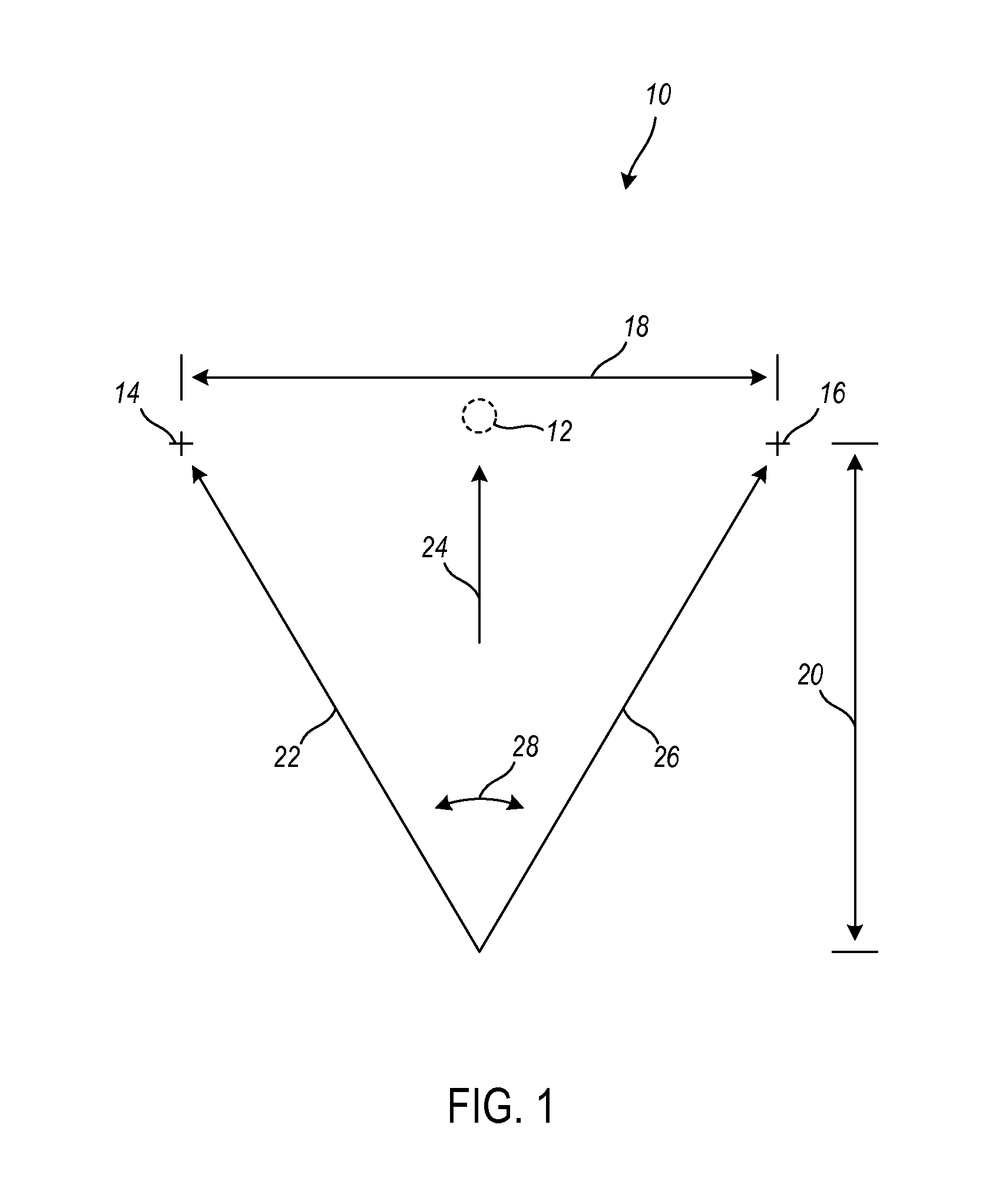
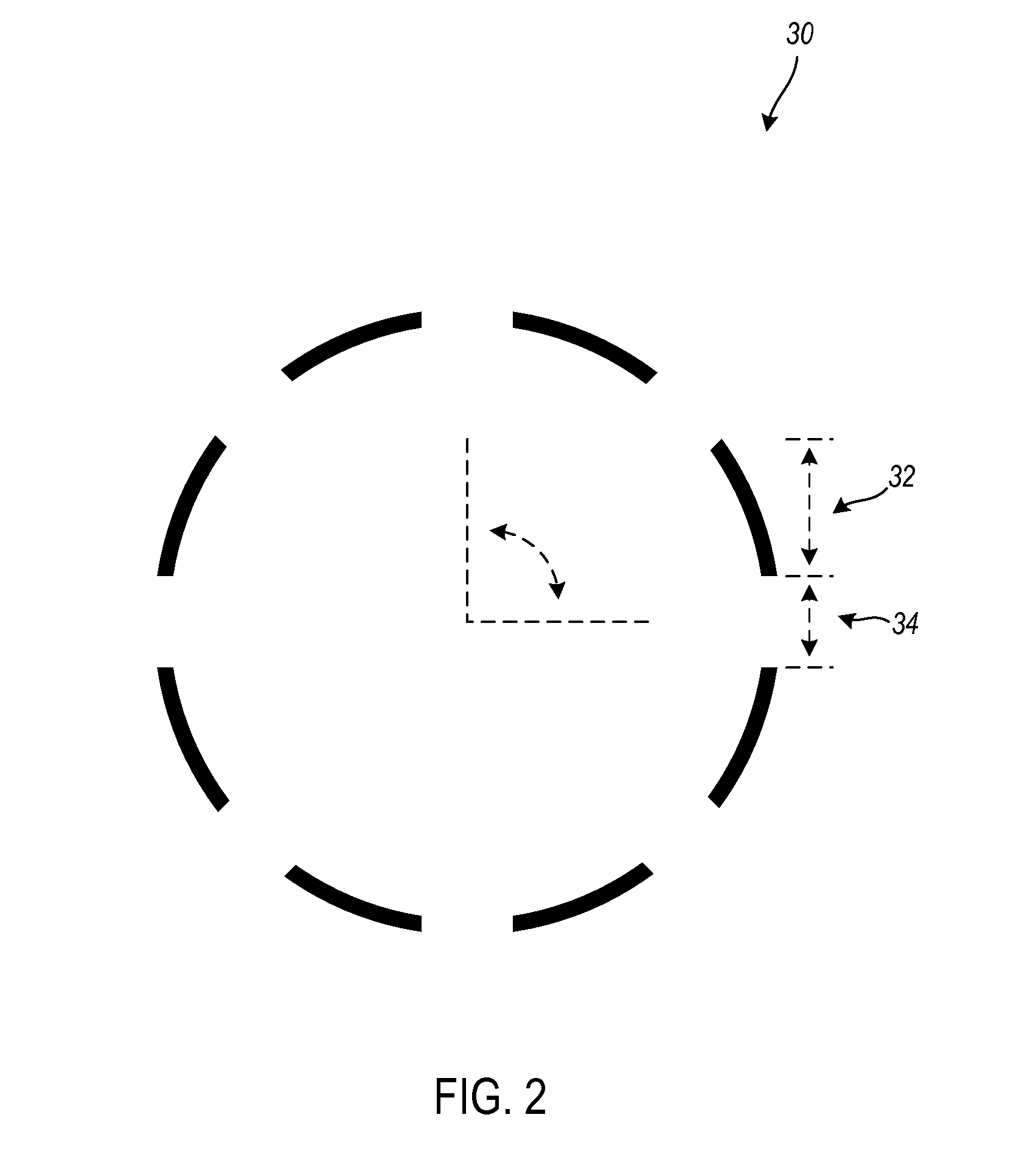
[0048]A dynamic optotype is a rotating geometric figure, such as a segmented circle, a triangle, or other shape having dimensions and a rotation rate such that its motion can just be perceived at a specified viewing distance by a subject whose vision is or has been corrected to the accepted 20 / 20 standard. Unlike static optotype tests, the dynamic optotype acuity test utilizes the p...


PUM


Abstract

A system and associated methods for animated image vision testing is disclosed. In at least one embodiment, a vision test includes at least one animated dynamic optotype image for measuring the visual acuity of a subject. The animated image vision test takes advantage of the ability of the human eyes to detect both distance and motion. Moving images, such as rotating segmented circles, let the eyes detect motion as to the size, distance, and rotation direction of that moving image. That motion detection is much more precise than the interpretation of multiple static letters or static images. Using rotating images for vision testing rather than static images creates an acuity test more accurate than current tests, a test that is faster to use, and a test that does not require the ability to read.

Description

CROSS-REFERENCE TO RELATED APPLICATIONS[0001]The present CIP patent application claims the benefit of priority of U.S. patent application Ser. No. 12 / 583,225 which is entitled “Animated Image Vision Test” filed on Aug. 17, 2009, and which is incorporated in full by reference herein.TECHNICAL FIELD[0002]The technology described herein relates generally to the field of vision testing devices and methods. More specifically, this technology relates to a device, system, and associated method for more accurately testing vision and acuity related to the correctness of prescriptions for eyeglasses and contact lenses.BACKGROUND ART[0003]The primary function of eyeglasses and contact lenses is in having the optical power of those lenses compensate for the loss of acuity (myopia) or excessive acuity (hyperopia) of the patient. Traditional vision acuity tests have used static optotypes as displays of printed or projected characters, objects, or shapes. Numerous patterns, configurations, and met...

Claims


Application Information

Patent Timeline
IPC IPC(8): A61B3/032
CPCA61B3/032
Inventor HYTOWITZ, ALLAN N.
Owner HYTOWITZ ALLAN N
Learn More