Connectors for communication, communication harness, and communication system
a technology for connecting cables and harnesses, applied in data switching networks, repeater/relay circuits, coupling device connections, etc., can solve the problems of not considering a configuration that contains a communication function, not enough to avoid redundant configuration, and simply mounting the transceiver on the built-in circuit board in the connector, so as to eliminate the giveaway of connectors and waste of harnesses
- Summary
- Abstract
- Description
- Claims
- Application Information
AI Technical Summary
Benefits of technology
Problems solved by technology
Method used
Image

Examples
embodiment 1
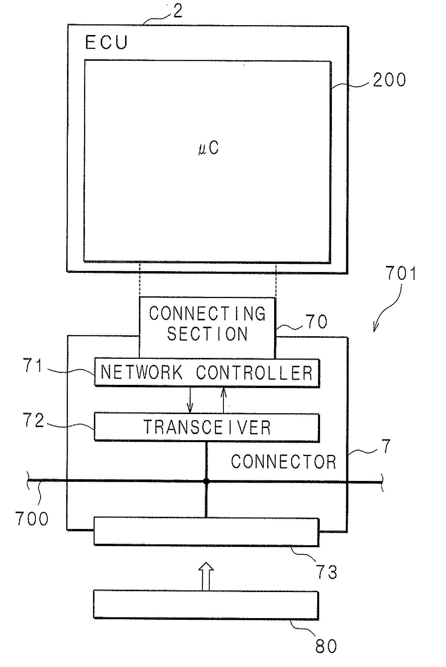
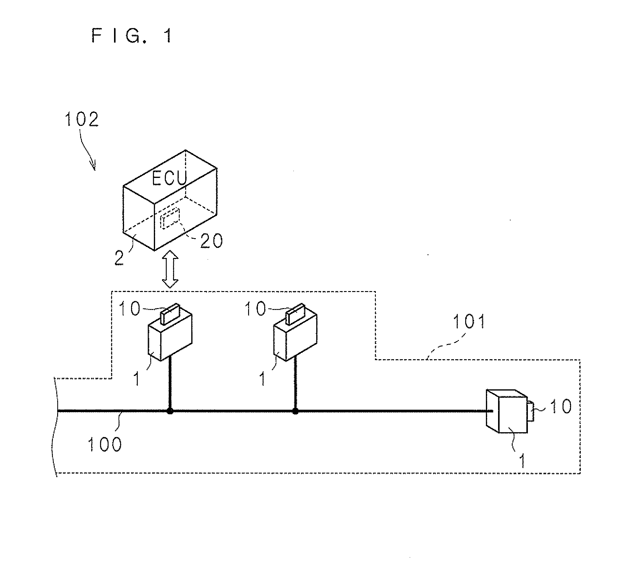
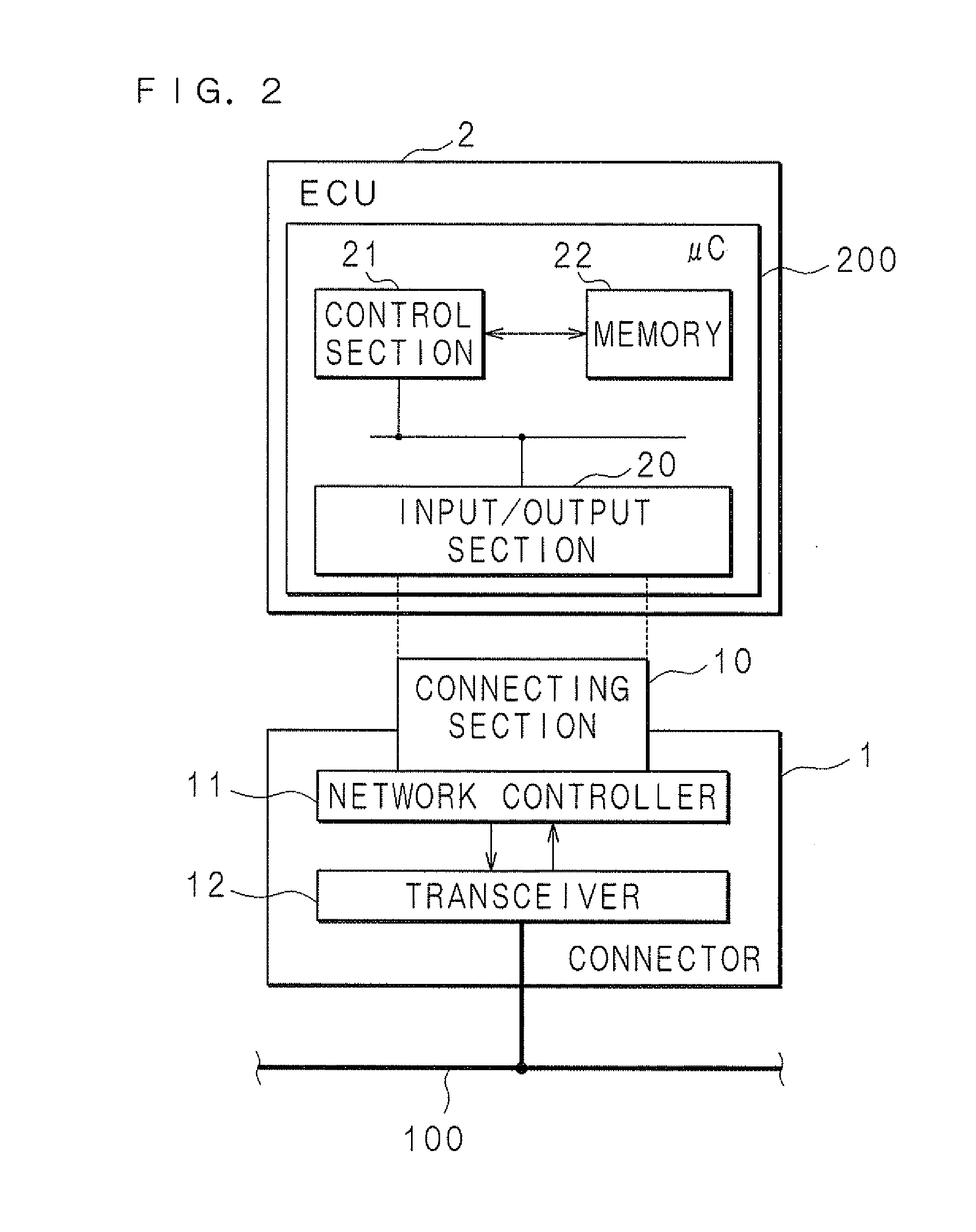
[0045]FIG. 1 is a configuration diagram schematically illustrating the configuration of a vehicle-mounted communication system 102 including connectors for communication according to Embodiment 1. FIG. 2 is a block diagram illustrating the internal structure of the connector and an ECU forming the vehicle-mounted communication system 102 according to Embodiment 1. The reference number 1 in FIG. 1 indicates a connector for communication including a connecting section 10 formed of a plug that is connected to be fit in a receptacle of an input / output section 20 in an ECU 2. A plurality of the connectors 1 connected to a communication line 100 are included in a communication harness 101 as shown in FIG. 1.
[0046]The ECUs 2, 2, . . . cooperate together by being connected to the connectors 1, 1, . . . respectively in the vehicle-mounted communication system 102. This allows the system 102 to realize various functions such as vehicle running control and sensor / actuator control related to a ...
embodiment 2
[0063]In Embodiment 2, an example of a vehicle-mounted communication system is described in which a connector that contains a GW (Gateway) function for expanding a communication system is further included. FIG. 3 is a block diagram illustrating a configuration of a vehicle-mounted communication system 104 according to Embodiment 2. Since the configuration of the vehicle-mounted communication system 104 of Embodiment 2 is similar to that of the vehicle-mounted communication system of Embodiment 1, the same reference numbers are assigned to the common structures and the detailed explanation will not be repeated.
[0064]The reference number 3 in FIG. 3 indicates a GW (Gateway) connector having a relaying function. A communication line 103 that is different from a communication line 100 is connected to the GW connector 3. ECU 4, 4, . . . similar to the ECU 2 are connected to the communication line 103. The GW connector 3 is connected to be interposed between the connector 1 and the ECU 2....
embodiment 3
[0073]In Embodiment 2, the connector 1 is configured to be connected to the ECU 2 with the GW connector 3 interposed in between. As the relaying function is not indispensable here, only a bus bar to branch the communication signal of the communication line 100 may be enough. FIG. 4 is a block diagram illustrating the configuration of a vehicle-mounted communication system 105 according to Embodiment 3. A configuration of the vehicle-mounted communication system 105 of Embodiment 3 is similar to that of the vehicle-mounted communication system of Embodiment 1 or 2, the same reference numbers are assigned to the common structures and the detailed explanation will not be repeated.
[0074]The reference number 5 in FIG. 4 indicates a connector for communication of Embodiment 3. The connector 5, having a shape similar to the connector 1 of the Embodiment 1, includes a network controller 51 and a transceiver 52 therein in addition to a connecting section 50. As the network controller 51 and ...
PUM
 Abstract
Description
Claims
Application Information