
Adjustable masonry arch form

a masonry arch and shape technology, applied in the direction of girders, joists, transoms, etc., can solve the problems of many waste of bricks, inability to use practice, and inability to adapt the contours of arched construction materials, etc., to achieve the effect of saving time and expense, reducing waste of materials, and increasing strength

Inactive Publication Date: 2005-02-01
BAILEY MICHAEL EUGENE
View PDF18 Cites 13 Cited by
  • Summary
  • Abstract
  • Description
  • Claims
  • Application Information

AI Technical Summary

Benefits of technology

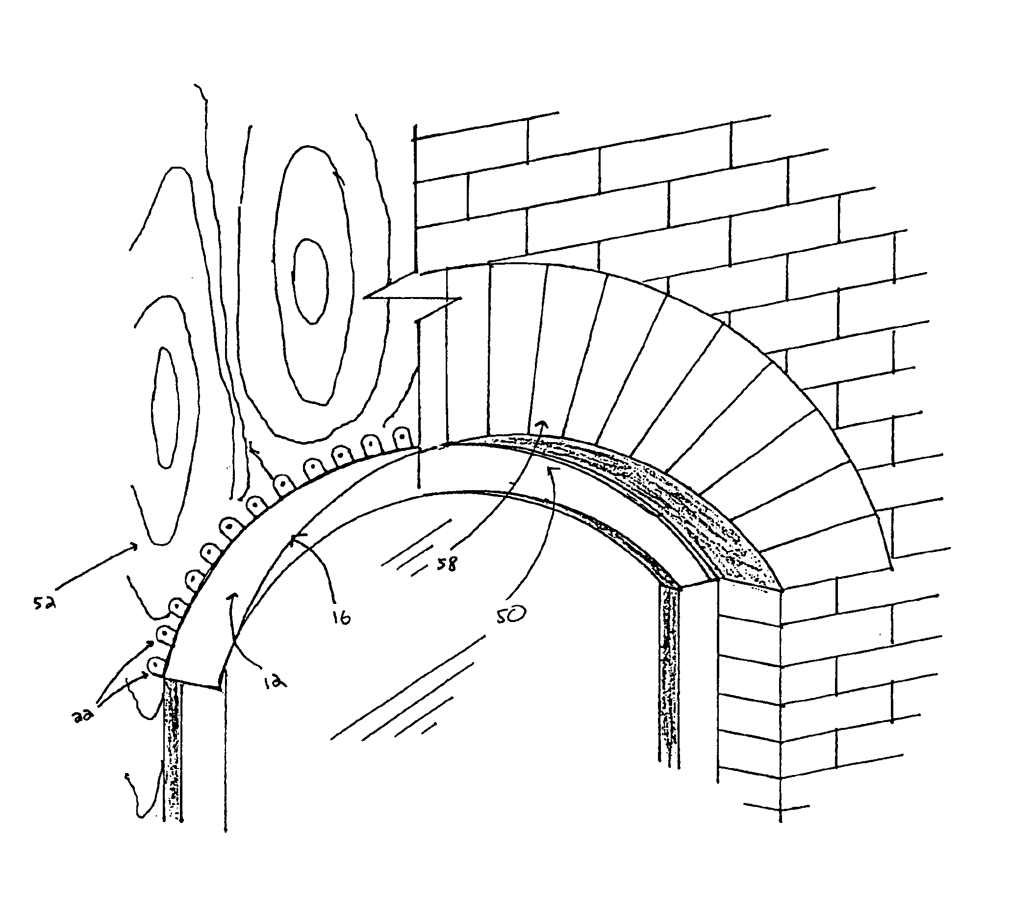
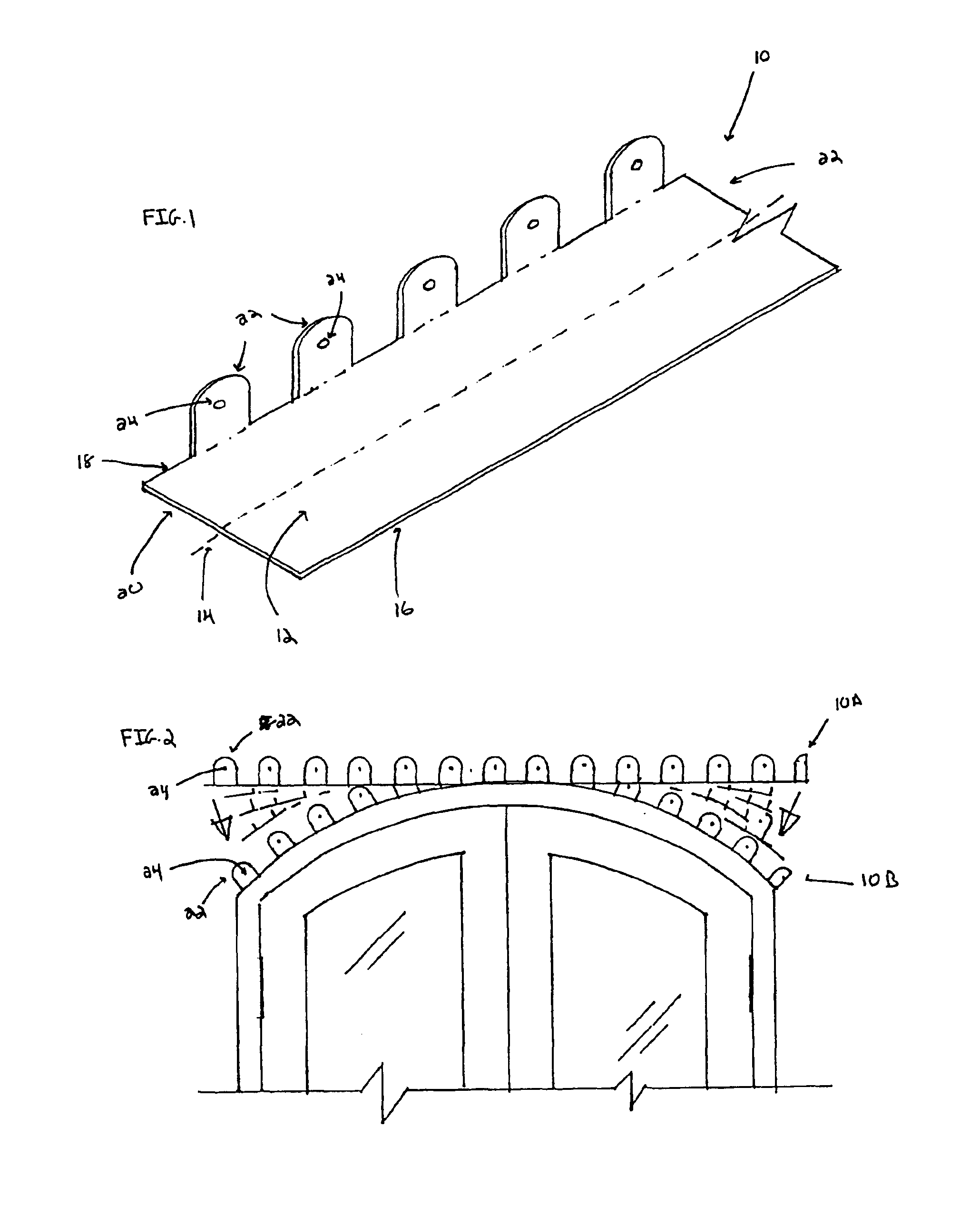
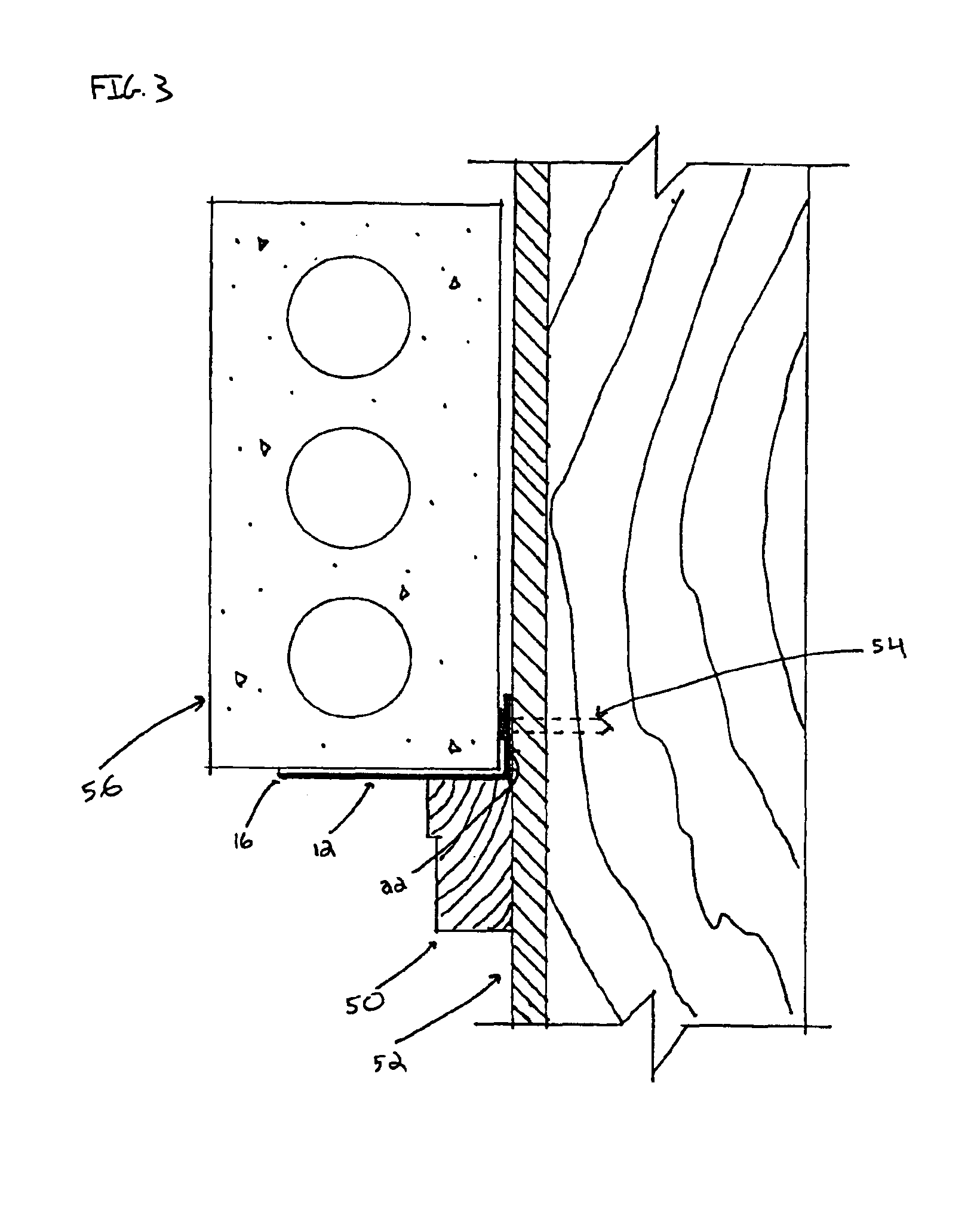
The adjustable masonry arch form of the present disclosure is an improvement over current devices available for installing masonry arches. The adjustable masonry arch form comprises a planar base section to support the masonry elements which will comprise the masonry arch, and a plurality of attachment means secured to the planar base for securing the form to a structure. In the embodiment illustrated, the attachment means is shown as a rounded flange. The adjustable masonry arch form is constructed from material rigid enough to support the masonry elements, but flexible enough to be bent to conform to any given arched construction. The adjustable masonry arch form is secured to the exterior of a structure by a securing means, such as screws, nails or staples. The masonry elements which will comprise the masonry arch are placed directly on the planar base of the form in the desired configuration and secured in the masonry arch by mortar. The form is left in position permanently, obviating the need to build a temporary arch support saving time and expense and obviating waste of materials, while providing additional strength to the arched construction. In addition, there is no repair required to the exterior surface of the structure.
Therefore, it is an object of the disclosure to provide an adjustable masonry arch form that is capable of being installed in any given arched construction at a construction site without the need to create or special order individually configured arch forms. It is another object of the disclosure to provide an adjustable masonry arch form that is permanently installed in an arched construction, thereby obviating the time consuming and wasteful practice of creating temporary forms, and which provide additional strength to the masonry arch. An additional object of the disclosure is to provide an adjustable masonry arch form such that the planar base and / or attachment means will not be deformed as the ach form is bent to conform to the contours of an arched construction. Yet another object of the disclosure to provide an adjustable masonry arch form that is economical to produce and simple to install, decreasing the overall cost of the finished arched construction. It is a further object of the disclosure to provide an adjustable masonry arch form that can be easily shipped, transported and stored, thereby minimizing the risk of damaging the form and avoiding costly construction delays caused by ordering replacement arch forms. It is also an object of the disclosure to provide an adjustable masonry arch form that will prevent damage to the structural features over which masonry arches are installed. Additional objects and advantages will become apparent through the drawings and descriptions that follow.

Problems solved by technology

In arched constructions, this practice cannot be employed.
As stated above, the materials that lintels are constructed from (steel, wood, or reinforced concrete) cannot be easily adapted to fit the contours of an arched construction.
In addition to being very time consuming, such a method leads to many bricks being wasted.
However, these items must be specially ordered since the configuration of masonry arches varies from application to application, making a “standard” prefabricated arch form impractical.
As a result, these prefabricated supports are expensive.
In addition, the prefabricated supports create other problems.
Since the supports are prefabricated in the form of an arch, they are bulky to ship and store, further increasing their cost.
In addition, these preformed supports are more susceptible to damage during shipping and storage.
As a result, if the units are damaged, construction may be delayed while replacement supports are obtained.
In general, the methods are tedious and time consuming to implement.
As a result, the cost of the final construction can be increased dramatically.
In addition, the arched constructions lack the strength of the horizontal constructions because of the lack of a solid lintel.
This additional weight can cause damage.

Method used


Image

  • Adjustable masonry arch form
  • Adjustable masonry arch form
  • Adjustable masonry arch form

Examples


Embodiment Construction

The adjustable masonry arch form 10 is illustrated in FIGS. 1-4, where like numbers in the figures refer to like elements. As illustrated in FIG. 1, the form 10 is composed of a planar section 12. The planar section 12 comprises longitudinal axis 14, a front side 16 and a rear side 18 parallel to the axis 14, and two ends 20 and 22. The width of the planar section 12 is sufficient to support the masonry to be incorporated into the masonry arch. While the width can be varied as determined by individual applications as can be determined by one of ordinary skill in the art, in one embodiment the planar section 12 is 3 inches wide. For aesthetic purposes, it is desired that the width of the planar section 3 be slightly less than the width of the masonry elements to be incorporated into the masonry arch (as illustrated in FIG. 3). The form 10 can be manufactured in any length desired and can be cut to fit a given installation at the job site. A plurality of attachment means are secured t...


PUM

PropertyMeasurementUnit
widthaaaaaaaaaa
widthaaaaaaaaaa
lengthaaaaaaaaaa

Abstract

An adjustable masonry arch form is disclosed. The adjustable masonry arch form has a planar base section to support the masonry elements which will form the masonry arch, and a plurality of attachment elements secured to the planar base for securing the form to a structure. The adjustable masonry arch form is constructed from material rigid enough to support the masonry elements, but flexible enough to be bent to conform to any given arched construction without unwanted buckling of the form. The masonry elements which form the masonry arch are placed directly on the planar base of the form in the desired configuration and secured in the masonry arch by mortar. The form is left in position permanently, obviating the need to build a temporary arch support saving time and expense and obviating waste of materials.

Description

FIELD OF THE DISCLOSUREThe present disclosure relates generally to an improved device for use in masonry applications. In particular, the present disclosure relates to an adjustable masonry arch form to support masonry elements in an arched construction.BACKGROUNDIn building projects, such as residential homes and commercial buildings, ornamental masonry elements are often placed over / around various structural features for aesthetic purposes. This is especially common around windows and doors. As used in this specification, masonry elements / masonry shall mean stone, brick, or other earthen materials used for construction purposes, generally using mortar as a bond. The presence of masonry accents in a residential home can greatly increase its resale value, and provides the homeowner with the desired aesthetic look and feel he / she is seeking.The process of installing masonry elements over and / or around a desired structural feature varies depending on the shape of the desired structura...

Claims


Application Information

Patent Timeline
Patent Type & Authority Patents(United States)
IPC IPC(8): E04G21/18E04F13/02E04C3/02E04C3/38E04F13/06E06B1/00
CPCE04B1/7046E04C3/02E04C3/38E04F13/06E04G21/1841E04F2013/061E06B1/006E04C2003/023E04G21/1866
Inventor BAILEY, MICHAEL EUGENE
Owner BAILEY MICHAEL EUGENE
Learn More