Alignment guide with spirit level

a technology of aligning guide and spirit level, applied in the field of aligning guide with spirit level, can solve the problems of acetabular and femoral components, affecting the accuracy of positioning of cup inserters in surgery, and affecting the accuracy of positioning of cups

Inactive Publication Date: 2012-12-27
DUPUY INT LTD
View PDF21 Cites 60 Cited by
  • Summary
  • Abstract
  • Description
  • Claims
  • Application Information

AI Technical Summary

Problems solved by technology

An improperly positioned acetabular component can lead to dislocations of the hip joint, decreased range of motion, and eventual loosening or failure of one or both of the acetabular and femoral components.
Incorrect acetabular component positioning can lead to edge loading and undesirable effects across bearings composed of any material, such as dislocation, increased wear, ceramic squeaking, elevated metal ion release and fractures.
Surgeons often have difficulty in performing this step as he or she must manipulate the cup in three dimensions while attempting to correct for angular changes that occur when translating the pre-operative radiographic angle into operative angles.
Thus, a common cause of malpositioning is the difference between the radiographic angles provided in the pre-operative plan and the operative angles observed by the surgeon.
The disadvantage of using operative angles in surgery is that, as you vary operative anteversion, the radiographic inclination angle of the cup changes.

Method used


Image

  • Alignment guide with spirit level
  • Alignment guide with spirit level
  • Alignment guide with spirit level

Examples


first embodiment

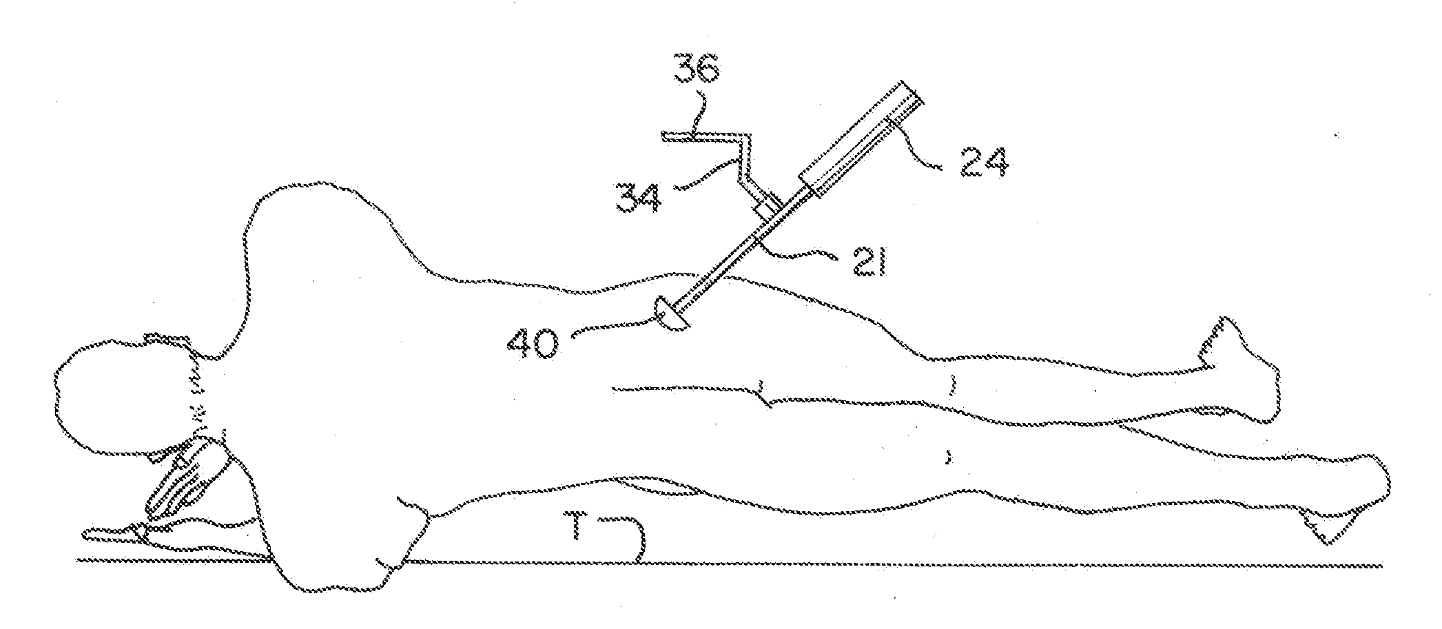
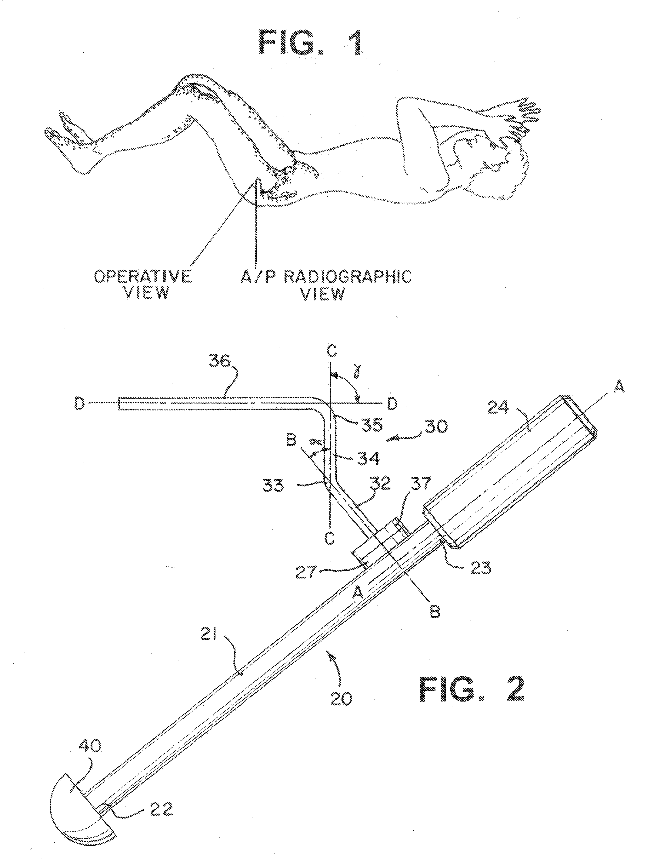
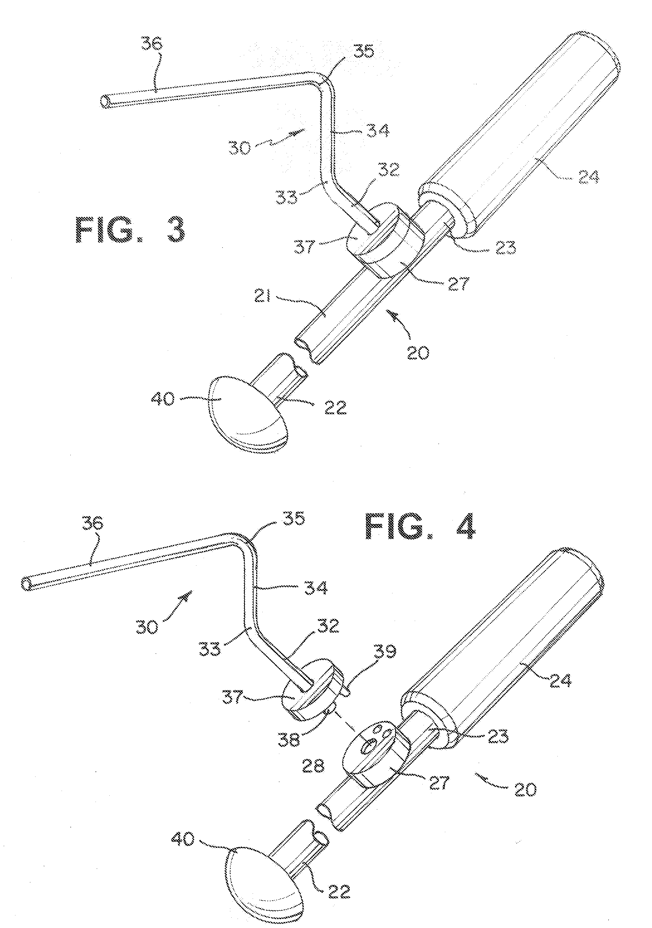
[0041]Referring to FIGS. 2 and 3, the alignment guide is generally referenced as reference numeral 20. Alignment guide 20 includes a shaft 21 having a longitudinal axis A and a guide arm, generally referenced as reference numeral 30, releasably attached to shaft 21. Alignment guide 20 may be attached to a cup or trial 40 at distal end 22 of shaft 21. Alignment guide 20 may include a handle 24 attached at proximal end 23 of shaft 21. Guide arm 30 may be attached to shaft 21 such that shaft 21 and guide arm 30 are co-planar in a first position. Guide arm 30 is preferably configured such that guide arm 30 may be detached from shaft 21, rotated to a second position about a first axis B substantially perpendicular to the longitudinal axis A at which position guide arm 30 is out of plane with shaft 1, and then re-attached to shaft 21. Alternatively, guide arm 30 may be spring biased with respect to shaft 21 such that a user could apply a force to overcome the spring bias to separate guide...

third embodiment

[0049]Referring to Referring to FIGS. 6-9, an alignment guide 220 is depicted. Similar structures are labelled similarly to the corresponding structures of the prior embodiments. Alignment guide 220 includes a shaft 221 having a longitudinal axis A, and a guide arm, generally indicated as reference numeral 230, releasably attached and rotatably attached to shaft 221. Alignment guide 220 may be attached to a cup or trial (not shown) at distal end 222 of shaft 221. Alignment guide 120 may include a handle 224 attached at proximal end 223 of shaft 221. Guide arm 230 may be attached to shaft 221 such that shaft 221 and guide arm 230 are co-planar in a first position. Guide arm 230 is preferably configured such that guide arm 230 may be rotated to a second position about a first axis B substantially perpendicular to the longitudinal axis A at which position guide arm 230 is out of plane with shaft 221. Preferably, guide arm 230 is rotatable in angular increments with respect to shaft 221...

fourth embodiment

[0066]Referring to FIG. 8, the alignment guide is generally referenced as reference numeral 320. Alignment guide 320 includes a shaft 321, having a longitudinal axis A, a guide arm, generally referred to as element 330, which is rotatable with respect to shaft 321, and a spirit level 380 attached to guide arm 330. This embodiment differs from the prior embodiments in that it includes spirit level 380, which facilitates the use of the alignment guide by making it easier for the user to visualize when the alignment guide is in the planned orientation. For example, it may be difficult for the surgeon to judge whether the guide arm is aligned with the patient axis while he or she is holding the device. As such, the spirit level provides an additional indicator allowing the surgeon to check the angle without having to alter his or her viewing position.

[0067]As with prior embodiments, alignment guide 320 may be attached to a cup or trial 340 at distal end 322 of shaft 321. Alignment guide...


PUM


Abstract

An alignment guide is described that includes a shaft having a longitudinal axis and a housing attachable to the shaft and rotatable about a first axis that is substantially perpendicular to the longitudinal axis. A guide arm the extends from the housing at a predetermined angle along a second axis. A spirit level is connected to the housing on a plane aligned with the predetermined angle.

Description

[0001]The present invention relates to an alignment guide. In particular, the present invention relates to an alignment guide for aligning an instrument, more particularly an alignment guide for use with the implantation of a hip cup.BACKGROUND OF THE INVENTION[0002]Hip replacement surgery typically is performed to compensate for severe damage of the acetabulum due to disease, trauma or other factors, and includes the steps of removing all or part of the existing joint and substituting for the removed bone a femoral component attached to the patient's femur and an acetabular cup attached to the patient's acetabulum. The prosthetic acetabular cup is implanted to substitute for the socket of the hip joint, and is mated with a prosthetic femoral component to complete the hip replacement surgery. In order to achieve optimal performance of the combined acetabular and femoral prostheses, the acetabular cup must be properly positioned in the acetabulum. An improperly positioned acetabular ...

Claims


Application Information

Patent Timeline
Patent Type & Authority Applications(United States)
IPC IPC(8): A61B17/56
CPCA61F2002/4687A61B17/8872A61F2/4609A61F2002/4668
Inventor BIRKBECK, ALECFREEMAN, ROBERTMOORE, GARYGOWERS, STEVEN
Owner DUPUY INT LTD
Why Eureka
Try Eureka