Method and device for monitoring the alignment of a measuring instrument, and measuring instrument

a technology for measuring instruments and alignments, applied in the direction of instruments, weighing apparatus details, weighing apparatuses, etc., can solve the problems of failure of monitoring devices, both kinds of errors can have serious consequences, and the rule is not always adhered to in practice, so as to achieve cost-effective design, simple configuration, and precise detection

Active Publication Date: 2008-02-05
METTLER TOLEDO GMBH
View PDF24 Cites 15 Cited by
  • Summary
  • Abstract
  • Description
  • Claims
  • Application Information

AI Technical Summary

Benefits of technology

[0012]In particular, the objective of the present invention calls for a method and a monitoring device that ensure a precise detection when at least one limit value for the inclination angle is exceeded and substantially avoid the problem of false messages or false alarms.
[0013]In addition, the monitoring device should have a simple configuration and a cost-effective design and it should be simple to use in a balance or in other measuring devices. Furthermore, the monitoring performance should not be negatively affected by changes in the properties of components such as electrical and optical elements nor by extraneous factors such as stray light.
[0019]Thus, it is possible to detect and correct changes in the intensity of the radiation emitted by the emitter element and / or received by the reference elements, for example due to a change in the power supplied to the emitter element or due to a color change of the elements in the light path. If the light intensity from the emitter element is, e.g., too low, the foregoing arrangement prevents the problem that the bubble is erroneously assumed to be lying in the sensor axis and to be attenuating the light from the emitter element while the bubble is in fact in a position outside the sensor axis. In other words, a situation is prevented where the inclination is erroneously registered as being within the tolerance range. Conversely, if the light intensity from the emitter element is too high, the inventive arrangement also prevents the problem that the bubble is erroneously assumed to be lying outside the sensor axis where it would not attenuate the light from the emitter element while the bubble is in fact centered on the sensor axis. Thus, the inventive arrangement also prevents a situation where the inclination is erroneously registered as being outside of the tolerance range.
[0022]In a preferred embodiment, the inclination sensor or spirit level is arranged on the housing in such a way that the position of the bubble can be visually verified, so that the electronic monitoring is supplemented with the possibility of a visual verification by the user. Because the radiating element is of a small size, it does not stand in the way of the visual inspection of the bubble. A possible interference from outside light with the electronic monitoring of the bubble is preferably prevented by selecting radiating, sensing, and reference elements working in a range of wavelengths such as for example the infrared range which lies substantially outside of the range of the interfering outside light.
[0032]With the use of the inclination counter, the intensity counter, the function counter and the error counter, it is possible to suppress momentary irregularities that may in some cases occur only once, so that unnecessary error messages are avoided.

Problems solved by technology

However, this rule is not always adhered to in practice.
With automatic monitoring, on the other hand, there can be failures in the monitoring device.
Both kinds of errors can have serious consequences.
With the first kind of error, the false alarms which are also referred to as “false positives” can cause an unnecessary interruption of the measurement or production process.
However, the position of the bubble can no longer be verified by visual inspection.

Method used


Image

  • Method and device for monitoring the alignment of a measuring instrument, and measuring instrument
  • Method and device for monitoring the alignment of a measuring instrument, and measuring instrument
  • Method and device for monitoring the alignment of a measuring instrument, and measuring instrument

Examples


Embodiment Construction

is presented below with reference to the drawings, wherein:

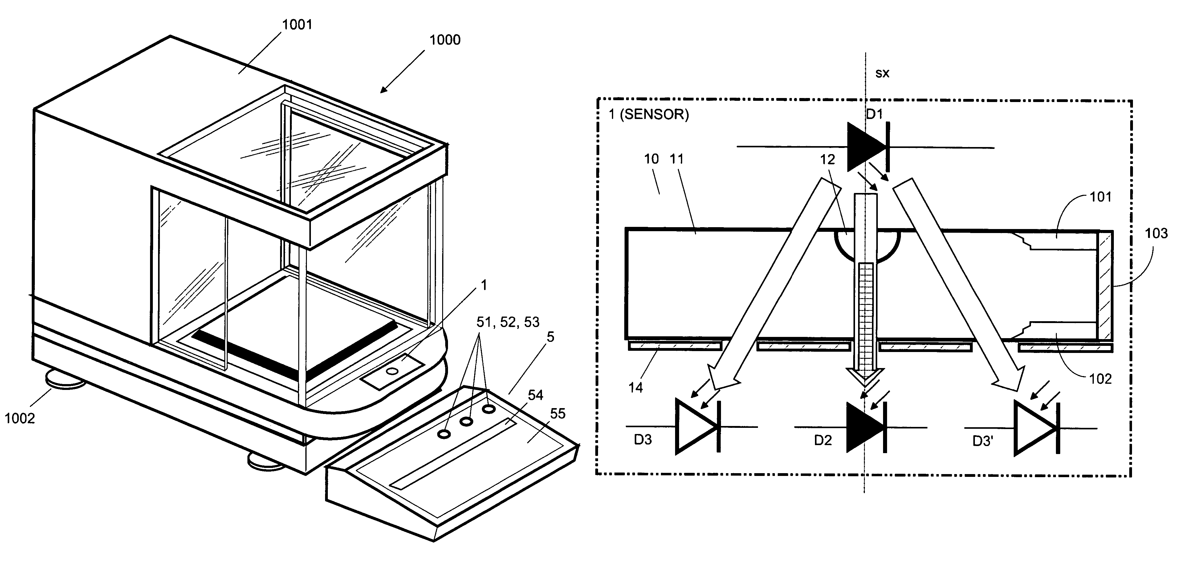
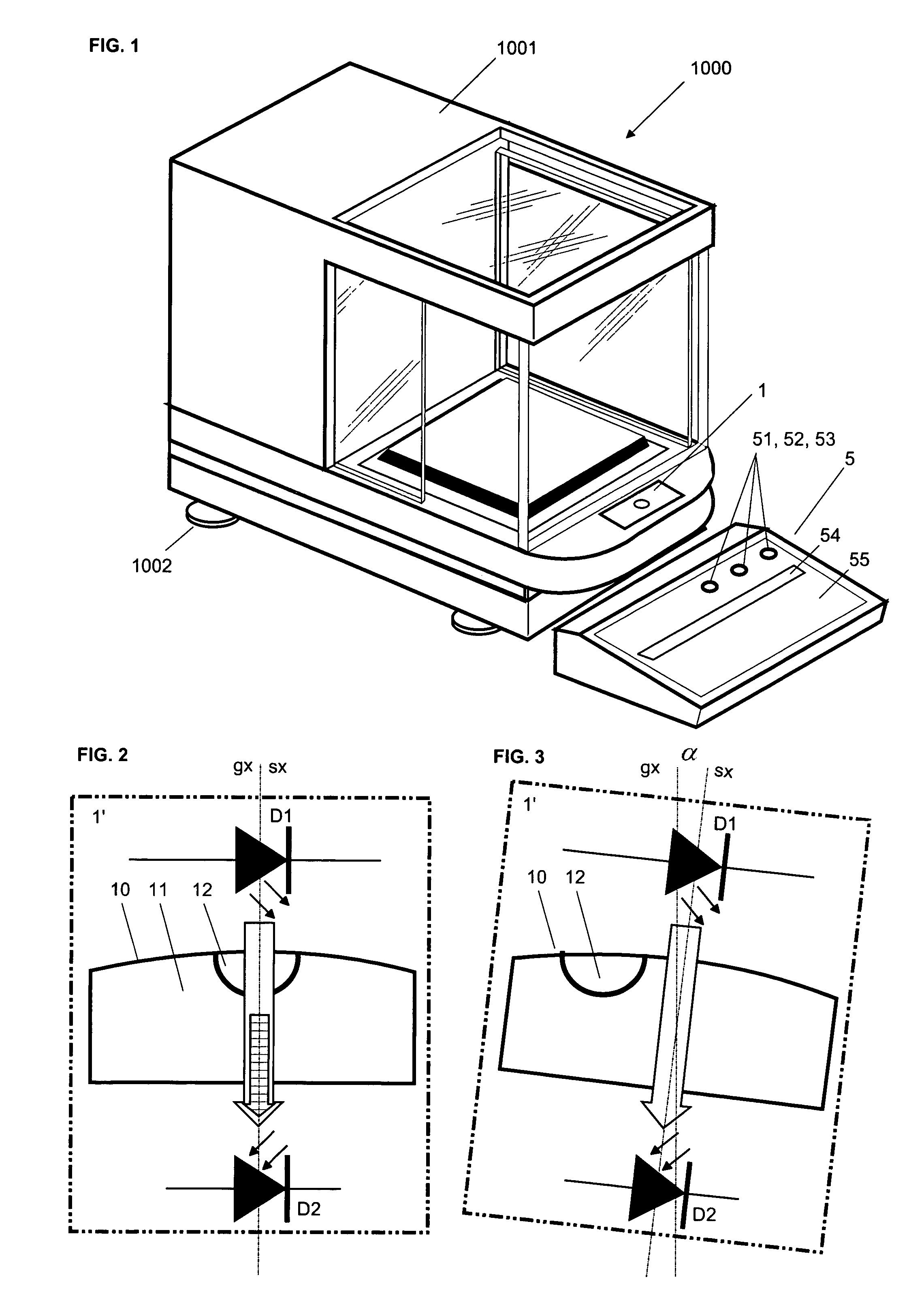
[0039]FIG. 1 represents a balance 1000 in accordance with the invention, with an inclination sensor 1 that is integrated in the balance housing in such a way that it is visible to the user;

[0040]FIG. 2 represents an inclination sensor 1′ whose sensor axis sx is aligned with the axis gx of the gravity force and which consists of a spirit level with a cylindrical container 10 that is closed off at both ends by transparent plates and filled with a liquid 11 leaving a bubble 12, with a radiation-emitting element D1 arranged above and a sensor element D2 arranged below the inclination sensor;

[0041]FIG. 3 represents the inclination sensor 1′ of FIG. 2 in an inclined position tilted to the right;

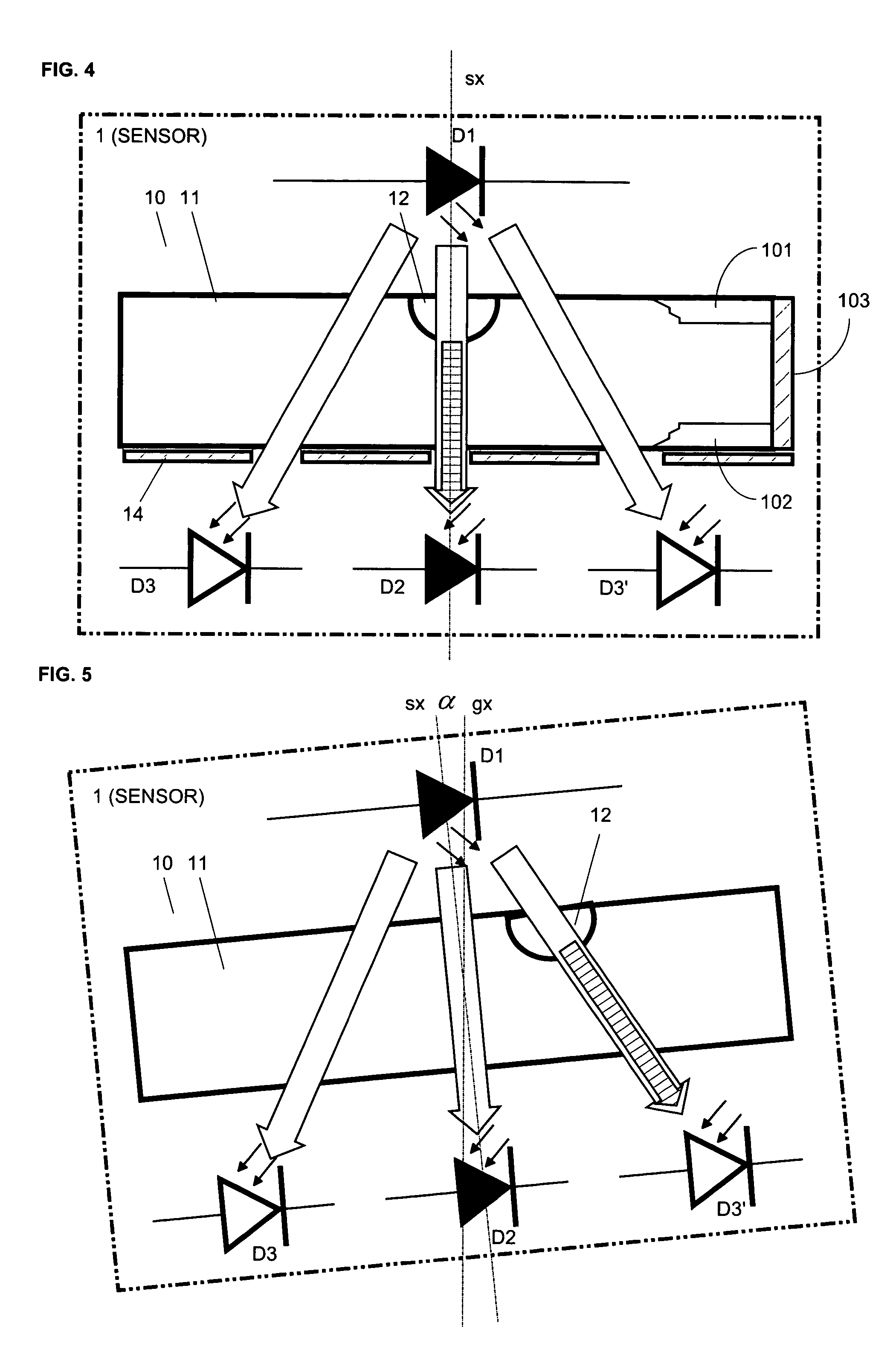
[0042]FIG. 4 represents an inclination sensor 1 in accordance with the invention consisting of a spirit level analogous to FIG. 2, with a radiation-emitting element D1 arranged above and a sensor element D2 as well as two reference elements...


PUM


Abstract

The method and the device serve to monitor the alignment of a measuring instrument, specifically a balance. To perform this function, the monitoring device is equipped with an inclination sensor based on the principle of a spirit level, with a container filled with a fluid in which a bubble is formed. According to the invention, the position of the bubble is measured optically by means of a radiating element that is arranged on one side of the bubble and serves to emit a radiation, and a sensor element that is arranged on the opposite side of the bubble and serves to receive the radiation. The radiating element, preferably a light-emitting diode, and the sensor element, preferably a photodiode, together define the sensor axis (sx) on which the bubble is centered as long as the sensor axis runs parallel to the axis of the gravity force. Furthermore, the sensor element is flanked by at least two reference elements that are likewise receiving the radiation. The reference elements serve to test whether the intensity of the radiation is within a permissible range. A function test is performed automatically inside the monitoring device in order to verify that the monitoring device is functioning correctly.

Description

BACKGROUND[0001]The present invention relates to a method and a device for monitoring the alignment of a measuring instrument, wherein the monitoring device is equipped with an inclination sensor. The invention further relates to a measuring instrument, specifically a balance, which is equipped with the monitoring device.[0002]Measuring instruments, in particular gravimetric measuring instruments such as for example thermo-gravimetric instruments, gravimetric moisture-determination instruments, or balances, have to meet special requirements in regard to how they are set up at the place where they are used. This applies in particular to balances equipped with a weighing cell and a load receiver which are used for the gravimetric measurement of weights. Ideally, a balance is set up in a position where the measurement axis of the balance—i.e., the axis that should coincide with the line of action of the weight force of a weighing object to be measured—runs in the direction of the gravi...

Claims


Application Information

Patent Timeline
Patent Type & Authority Patents(United States)
IPC IPC(8): G01C9/06G01G23/00G01C9/32
CPCG01C9/06G01G23/002G01C2009/066
Inventor KUNZI, HANSRUEDILEISINGER, ROGER
Owner METTLER TOLEDO GMBH
Why Eureka
Try Eureka