
Method for controlling a transmission brake

a transmission brake and brake technology, applied in the direction of instruments, mechanical equipment, gearing, etc., can solve the problems of certain inaccuracy of methods, and achieve the effect of further improving the upshifting quality of transmissions

Active Publication Date: 2012-12-27
ZF FRIEDRICHSHAFEN AG
View PDF10 Cites 8 Cited by
  • Summary
  • Abstract
  • Description
  • Claims
  • Application Information

AI Technical Summary

Benefits of technology

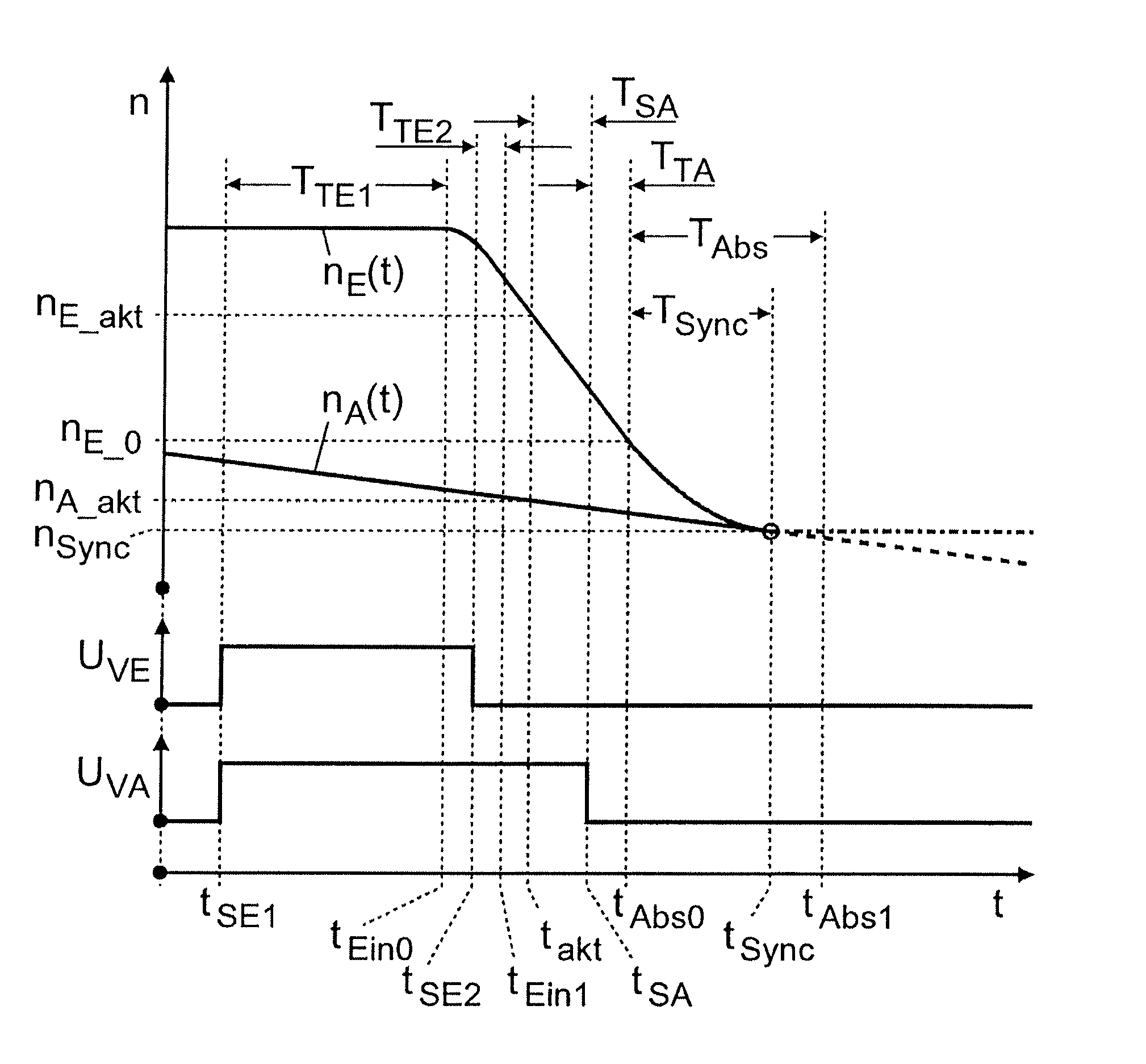
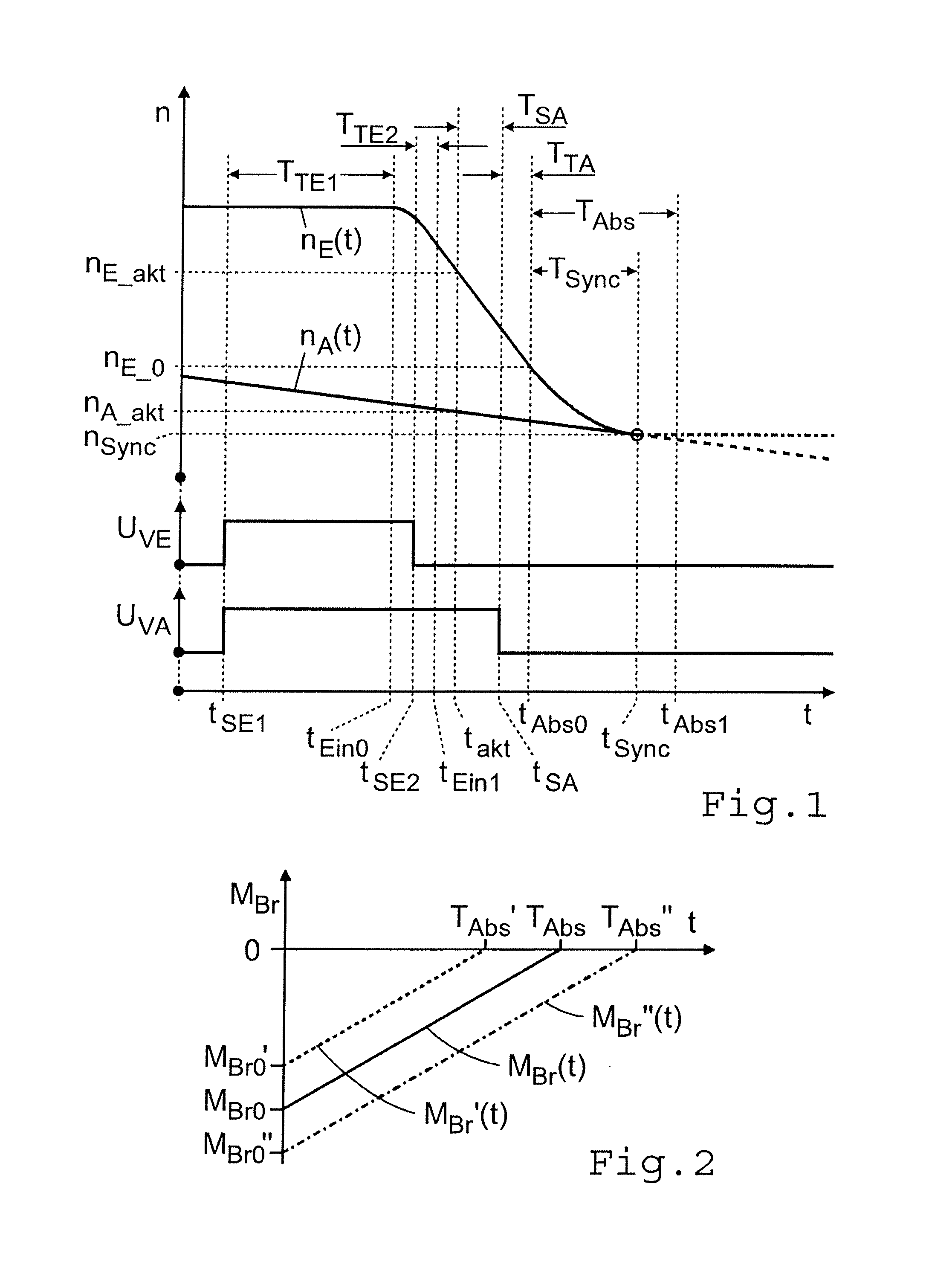
[0009]Accordingly, the purpose of the present invention is to indicate a method for controlling a transmission brake of the type mentioned earlier, in an automated variable-speed transmission of countershaft design and provided with claw clutches, by virtue of which the control properties of the transmission brake are taken into account more accurately so that the shifting quality of upshifts of the transmission is further improved.

Problems solved by technology

However, since particularly with an arrangement of the loose wheels on the countershaft and the output shaft alternating in pairs it would be relatively complicated to convert the respective speeds at the relevant transmission shaft for the gear clutch of the target gear concerned, it is usual to refer the two speeds, in each case independently of the arrangement of the loose wheel concerned, uniformly to the same transmission shaft, preferably the input shaft.
In this known method, however, the steady decrease of the braking torque of the transmission brake during the disengagement process and the influence of operating parameters, such as the operating temperature of the transmission brake, on the response behavior and the disengagement process are not explicitly determined and are consequently taken into account only approximately by the lead time, which results in certain inaccuracy of the method.

Method used


Image

  • Method for controlling a transmission brake
  • Method for controlling a transmission brake
  • Method for controlling a transmission brake

Examples


Embodiment Construction

[0040]FIG. 4 shows a typical transmission brake 1 in an automated transmission of countershaft design provided with claw clutches, with which the control method according to the invention can be used. The transmission brake is in the form of a hydraulically or pneumatically actuated disk brake and is in this case arranged at the engine-side end of a countershaft 2 of the transmission (which is not illustrated further). The inner and outer disks 3, 4 of the transmission brake 1 are connected in a rotationally fixed manner by way of inner and outer carrier teeth, in alternation to the countershaft 2 and to a brake housing 6 mounted on an end wall 5 of the transmission housing on the engine side. The transmission brake 1 is actuated by a piston 8 fitted to move axially in a brake cylinder 7, which is acted upon on the outside by the controllable control pressure in the pressure space 9 of the brake cylinder 7 and thereby pressed against the disks 3, 4 in opposition to the restoring for...


PUM


Abstract

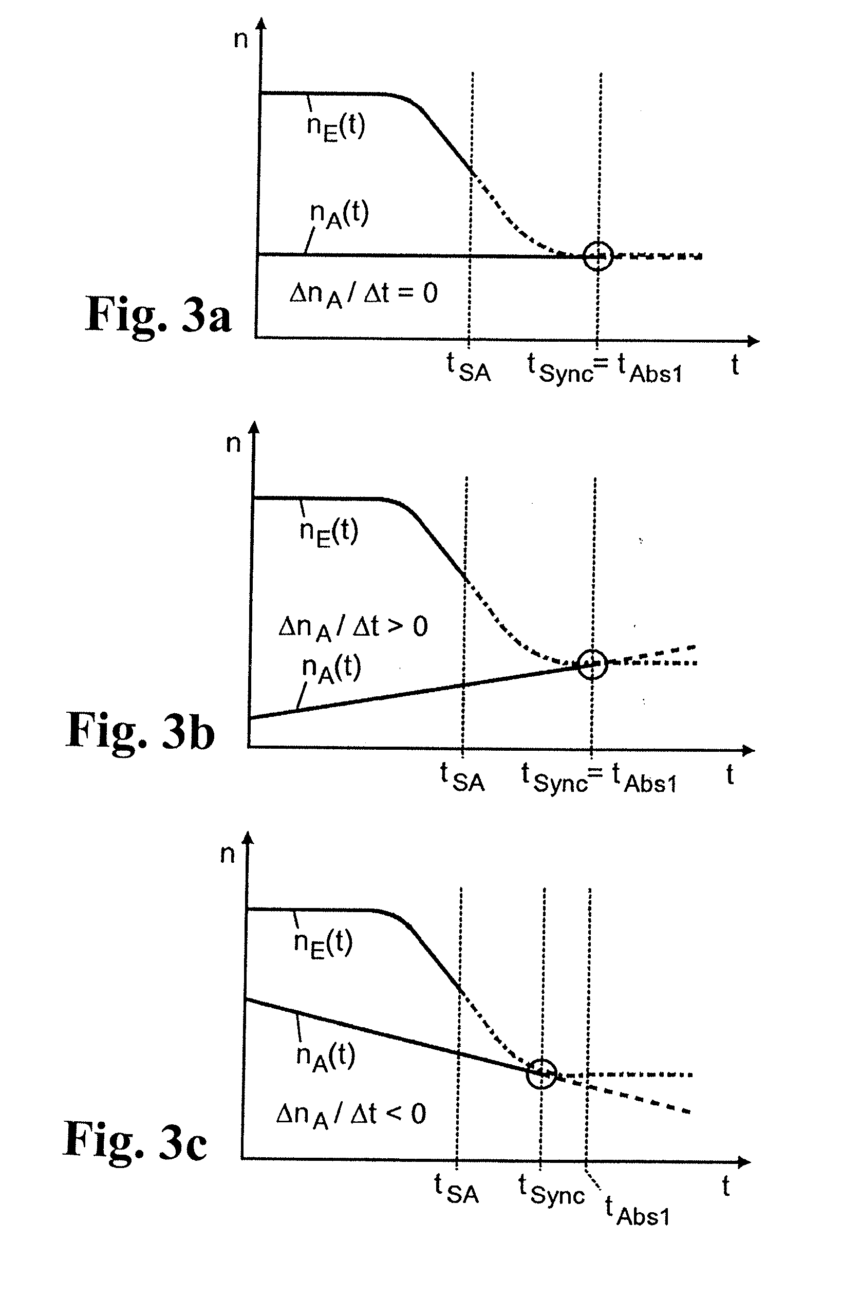
A method of controlling a transmission brake that is actuated by inlet and outlet valves. For determining when to transmit a disengagement signal for opening the outlet valve, the current input and output speeds are determined and the respective gradients of these speeds are calculated. Variation of the input speed, during the disengagement of the brake, is determined as a function of the input gradient, the optimum time for reaching the synchronous speed, during brake disengagement, is determined from the input speed variation as a function of the output gradient, and the time interval until transmission of the disengagement signal is determined as a function of the current input and output speeds and their gradients, by a back-calculation from the time when the synchronous speed is reached, taking a disengagement dead time of the brake, between transmitting the disengagement signal and start of disengagement, into account.

Description

[0001]This application is a National Stage completion of PCT / EP2011 / 052088 filed Feb. 14, 2011, which claims priority from German patent application serial no. 10 2010 002 764.2 filed Mar. 11, 2010.FIELD OF THE INVENTION[0002]The invention concerns a method for controlling a transmission brake of an automated variable-speed transmission of countershaft design provided with claw clutches, the brake being functionally connected to a transmission shaft on the input side and being hydraulically or pneumatically actuated by means of an inlet valve and an outlet valve each made as a 2 / 2-way magnetic switching valve, such that for an upshift from a gear under load to a target gear, once the loaded gear has been disengaged, for the synchronization of the target gear the inlet valve is first opened and the outlet valve is closed, once a braking torque has been set the inlet valve is closed, and during the braking of the transmission shaft on the input side the time until the output of a deac...

Claims


Application Information

Patent Timeline
Patent Type & Authority Applications(United States)
IPC IPC(8): F16H59/46G06F17/11
CPCB60W2050/006F16H59/40F16H59/42F16H61/0403F16H2003/123Y10T74/19637F16H2059/363F16H2059/405Y10T477/60Y10T74/19284F16H2061/0411B60W50/0097
Inventor GANSOHR, MARCUS
Owner ZF FRIEDRICHSHAFEN AG
Learn More