Slim keypad structure and electronic device using the same

a keypad and structure technology, applied in the direction of coding, pulse technique, instruments, etc., can solve the problems of difficult key identification, confusion and difficulty, and the inability of touch-screen operating interface to provide affirmative tactile feedback of structural keypads, and achieve the effect of easy assembly

Active Publication Date: 2013-01-03
LITE ON TECH CORP +1
View PDF3 Cites 9 Cited by
  • Summary
  • Abstract
  • Description
  • Claims
  • Application Information

AI Technical Summary

Benefits of technology

[0008]The instant disclosure provides a slim keypad structure that is structurally thin,

Problems solved by technology

Speedy development of portable smart electronics, such as mobile phone, PDA, and tablet PC, constantly pushes the demand for devices having lower physical profile.
However, the touch-screen operating interface cannot provide the affirmative tactile feedback of a structural keypad.
Moreover, having limited availab

Method used


Image

  • Slim keypad structure and electronic device using the same
  • Slim keypad structure and electronic device using the same
  • Slim keypad structure and electronic device using the same

Examples


second embodiment

[0035]Referring to FIG. 3A, which show the key cap according to the instant disclosure. The difference between the key cap 20a in this embodiment and the fore-mentioned embodiment is the fixing way. The key cap 20a uses a hook 22a at the bottom surface thereof to clip to two sides of the frame portion 12. Besides, the key cap 20a has a pair of resting portions 24a on the bottom surface thereof, so that it can be against the front portion and the rear portion of the frame portion 12 in a balance manner. The front bar 121 and the rear bar 123 of the frame portion. The resting portion 24a is also disposed on the bump 122.

[0036]Referring to FIG. 3B, which illustrates a third embodiment of the key cap according to the instant disclosure. The difference between this embodiment of the key cap 20b and the first embodiment is that the bottom surface of the key cap 20b only has a frame-shaped resting portion 24b, without positioning protrusion or hook. This embodiment uses an adhesive layer 2...

third embodiment

[0038]Referring to FIG. 3D, which is a side view of a supporting plate being uplifted of third embodiment according to the instant disclosure. This embodiment has an uplifted portion 52 integrally protruded upward from the bearing substrate 50. The uplifted portion 52 passes through the circuit board 40 and propped against the bottom surface of the supporting plate 10. The shape of the uplifted portion 52 could be in square column shape or half-column.

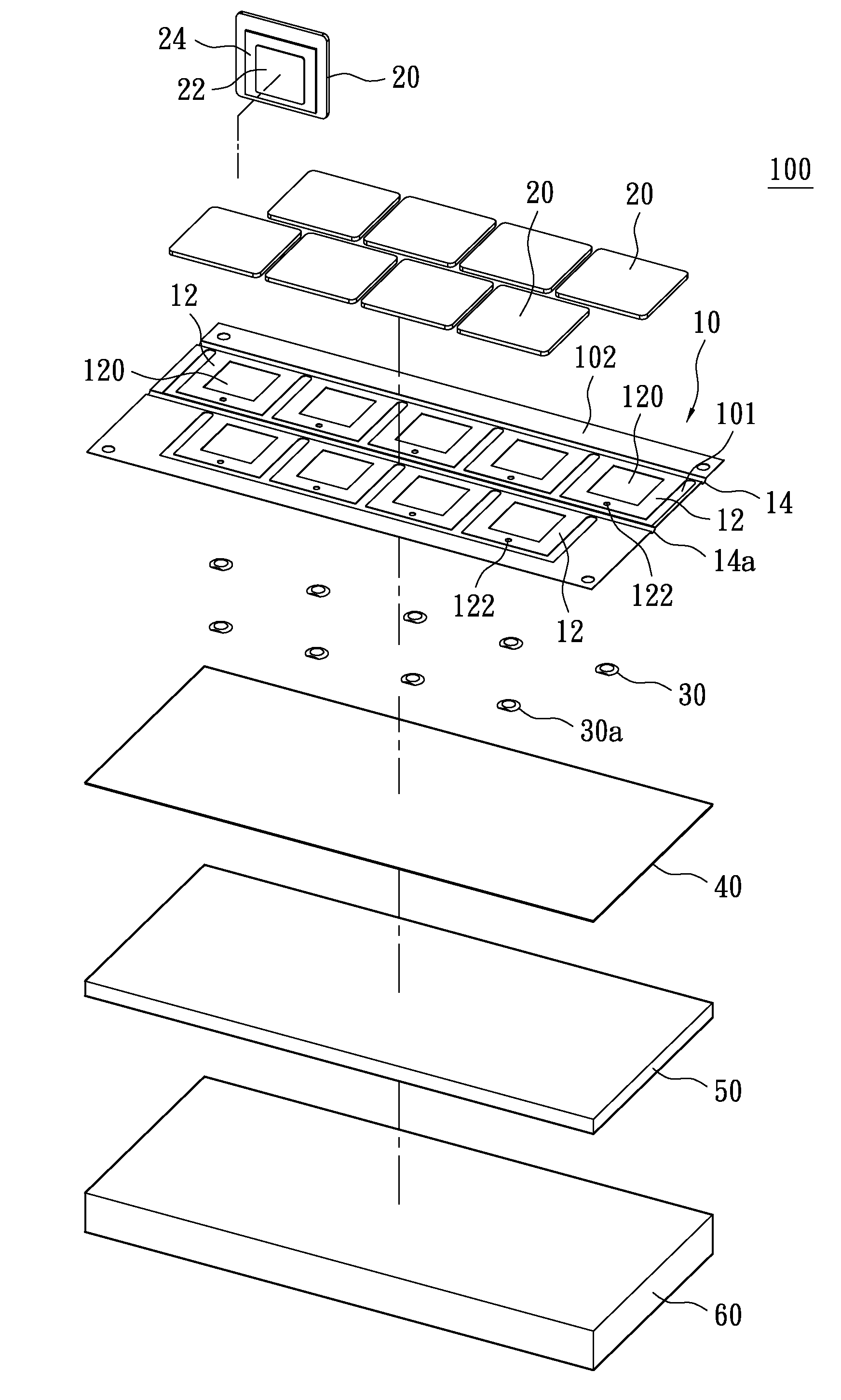
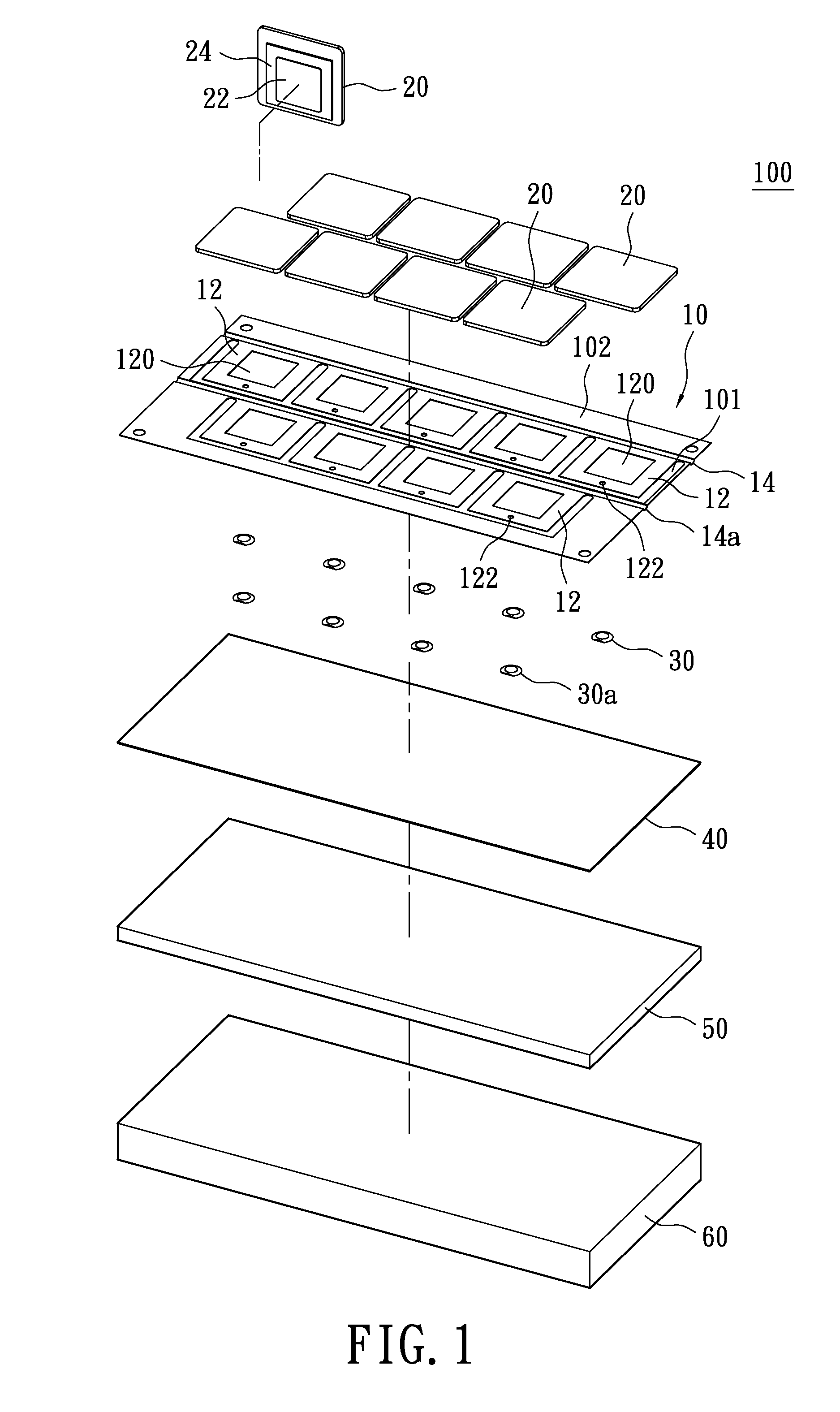
[0039]Referring to FIG. 1 and FIG. 3, the dome 30 is a metal slug in substantial half-sphere, which is disposed under the frame portion 12 opposite to the uplifted portion 14. When the key cap 20 is pressed, the dome 30 conducts a corresponding circuit on the circuit board 40 (not shown) to produce a signal and provides an elastic force. The circuit board 40 in this embodiment is made of light-transmissible material, and is printed with a plurality of conductive circuits under the domes 30 correspondingly.

[0040]The slim keypad structur...


PUM


Abstract

A slim key includes a supporting plate, at least one key cap, at least one dome and a light-permeable circuit board. The supporting plate is disposed above the circuit board and has at least one frame part. Each frame part is formed with a light-permeable hole at a central portion thereof. The key pad is disposed on the top surface of the frame part correspondingly. The circuit board has at least one conductive circuit formed thereon under the dome correspondingly. The dome is correspondingly disposed between the frame part and the circuit board. According to one embodiment, the instant disclosure also provides an electronic device with the slim keypad structure.

Description

BACKGROUND OF THE INVENTION[0001]1. Field of the Invention[0002]The instant disclosure is related to a slim keypad structure and electronic devices utilizing the same. In particular, the instant disclosure relates to a slim keypad structure particularly suitable for implementation in modern low-profile electronics, and an electronic device incorporating the slim keypad structure.[0003]2. Description of Related Art[0004]Speedy development of portable smart electronics, such as mobile phone, PDA, and tablet PC, constantly pushes the demand for devices having lower physical profile. With the improvement of touch-screen control interface, more and more electronic devices abandon the structural keypad in favor of the touch-screen input solution. However, the touch-screen operating interface cannot provide the affirmative tactile feedback of a structural keypad.[0005]Obviously, the key structure needs further refinement to improve its compatibility and adaptability with the development tr...

Claims


Application Information

Patent Timeline
IPC IPC(8): G06F3/02H03K17/94
CPCH01H13/7065H01H2219/036H01H2221/006H01H2221/05H01H2237/004H01H2229/042H01H2233/034H01H2233/074H01H2227/036
Inventor CHIANG, HSIAO-LUNG
Owner LITE ON TECH CORP
Why Eureka
Try Eureka