
Multi-port optical connection terminal assemblies supporting optical signal splitting, and related terminals and methods

a technology of optical connection terminals and assemblies, applied in the direction of optics, optical elements, instruments, etc., can solve the problems of small radius bends, cyclical and episodic movements of optical fibers, and the multi-port splitter box b>30/b> becoming too large, and achieves the effect of convenient installation

Active Publication Date: 2013-01-03
CORNING OPTICAL COMM LLC
View PDF6 Cites 47 Cited by
  • Summary
  • Abstract
  • Description
  • Claims
  • Application Information

AI Technical Summary

Benefits of technology

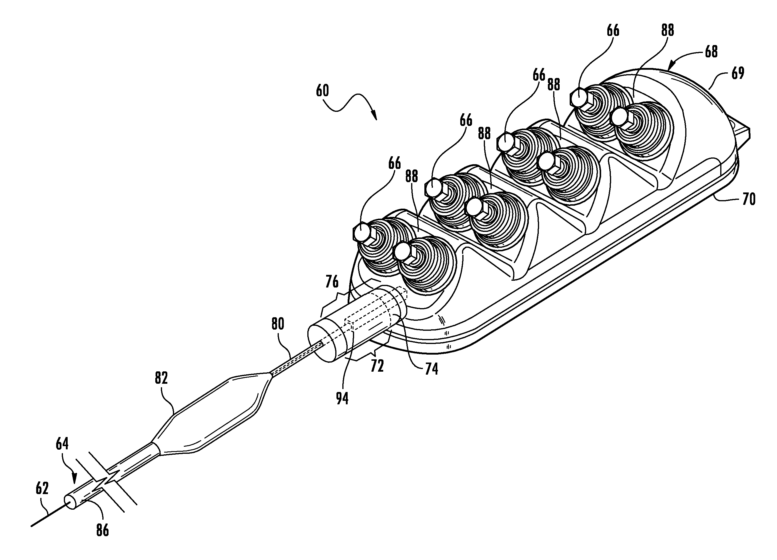
The patent describes a multi-port optical connection terminal assembly that includes an enclosure and an optical splitter. The optical splitter has an input optical fiber and multiple output optical fibers. The enclosure has an internal cavity and a plurality of optical connection nodes. The optical splitter is attached to the enclosure using a furcation structure, which creates a seal with the enclosure. This design allows for easier installation through narrow passageways and ducts, and it is less expensive to manufacture. The technical effects of this patent include improved installation flexibility and cost-effectiveness.

Problems solved by technology

Mechanical issues may include small-radius bends and cyclical and episodic movements of the optical fibers.
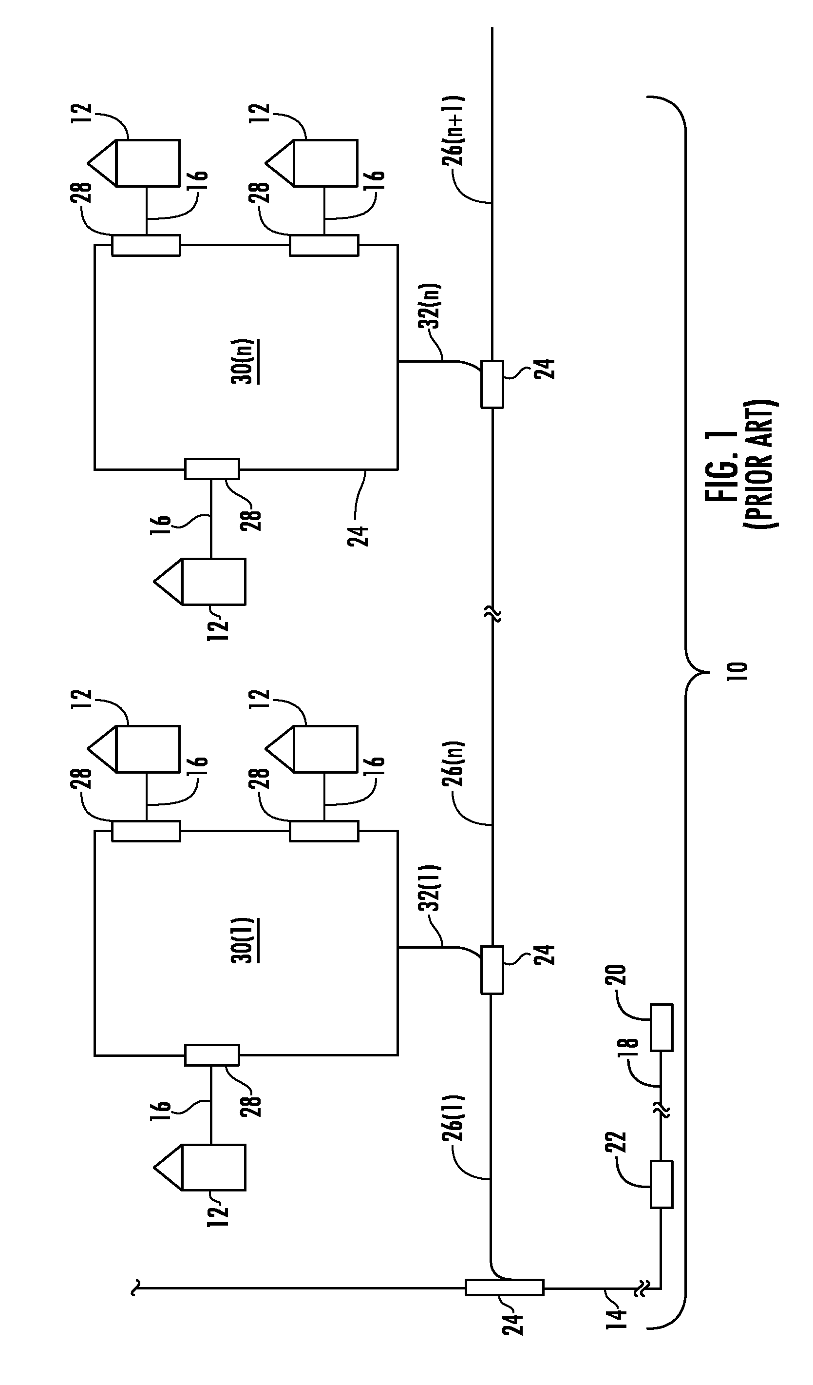
Environmental issues may be water when the output splitter box 30 is installed underground.
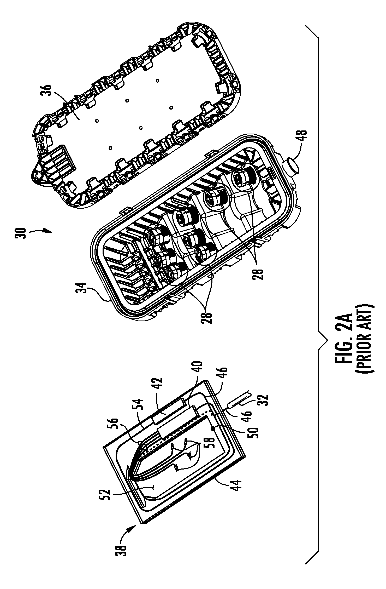
This conventional approach has resulted in the multi-port splitter box 30 becoming too large in many cases for installation in the field.

Method used


Image

  • Multi-port optical connection terminal assemblies supporting optical signal splitting, and related terminals and methods
  • Multi-port optical connection terminal assemblies supporting optical signal splitting, and related terminals and methods
  • Multi-port optical connection terminal assemblies supporting optical signal splitting, and related terminals and methods

Examples


Embodiment Construction

[0009]Embodiments disclosed in the detailed description include multi-port optical connection terminal assemblies, related terminals and methods. In one embodiment, a multi-port optical connection terminal assembly is disclosed. This multi-port optical connection terminal assembly may include an enclosure including an internal cavity, an input orifice, and a plurality of optical connection nodes. The multi-port optical connection terminal assembly may also include an optical splitter comprising a body, an input optical fiber, and plurality of output optical fibers. At least a portion of the body of the optical splitter may be disposed outside the internal cavity of the enclosure. The input optical fiber of the optical splitter may be disposed outside the internal cavity of the enclosure, and the plurality of the output optical fibers of the optical splitter may be disposed inside the internal cavity. In this manner, the enclosure of the multi-port optical connection terminal assembl...


PUM


Abstract

Multi-port optical connection terminal assemblies, related terminals and methods are disclosed herein. In one embodiment, a multi-port optical connection terminal assembly may include an enclosure including an internal cavity, an input orifice, and optical connection nodes. The multi-port optical connection terminal assembly may also include an optical splitter comprising a body, an input optical fiber, and output optical fibers. At least a portion of the body of the optical splitter may be disposed outside the internal cavity of the enclosure. The input optical fiber of the optical splitter may be disposed outside the internal cavity of the enclosure, and the plurality of the output optical fibers of the optical splitter may be disposed inside the internal cavity. In this manner, the enclosure of the multi-port optical connection terminal assembly is not required to be sized to completely contain the optical splitter.

Description

RELATED APPLICATIONS[0001]This application claims the benefit of priority under 35 U.S.C. §119 of U.S. Provisional Application Ser. No. 61 / 503,173 filed on Jun. 30, 2011, the content of which is relied upon and incorporated herein by reference in its entirety.BACKGROUND[0002]1. Field of the Disclosure[0003]The technology of the disclosure relates to multi-port optical connection terminals and assemblies which may be used to distribute optical signals from optical fibers.[0004]2. Technical Background[0005]Benefits of optical fiber use include extremely wide bandwidth and low noise operation. Because of these advantages, optical fiber is increasingly being used for a variety of applications, including but not limited to broadband voice, video, and data transmission. As a result, fiber optic communications networks include a number of interconnection points at which multiple optical fibers are interconnected. Fiber optic communications networks also include a number of connection termi...

Claims


Application Information

Patent Timeline
IPC IPC(8): G02B6/26G02B6/46G02B6/255
CPCG02B6/4441G02B6/4471Y10T29/49208Y10T29/4921Y10T29/49194G02B6/44765G02B6/44465G02B6/44515G02B6/44528
Inventor KINGSBURY, BRIAN DUANE
Owner CORNING OPTICAL COMM LLC
Learn More