Chordal mounting arrangement for low-ductility turbine shroud

a turbine and low-ductility technology, applied in the direction of machines/engines, stators, liquid fuel engines, etc., can solve the problems of bolt bending, creep, air leakage, wear, friction,

Inactive Publication Date: 2013-01-03
GENERAL ELECTRIC CO
View PDF12 Cites 45 Cited by
  • Summary
  • Abstract
  • Description
  • Claims
  • Application Information

AI Technical Summary

Problems solved by technology

While effective for mounting and positioning, the hanger or load spreader presents design challenges such as bolt bending, creep, air leaks, wear, and friction related problems.

Method used


Image

  • Chordal mounting arrangement for low-ductility turbine shroud
  • Chordal mounting arrangement for low-ductility turbine shroud
  • Chordal mounting arrangement for low-ductility turbine shroud

Examples


Embodiment Construction

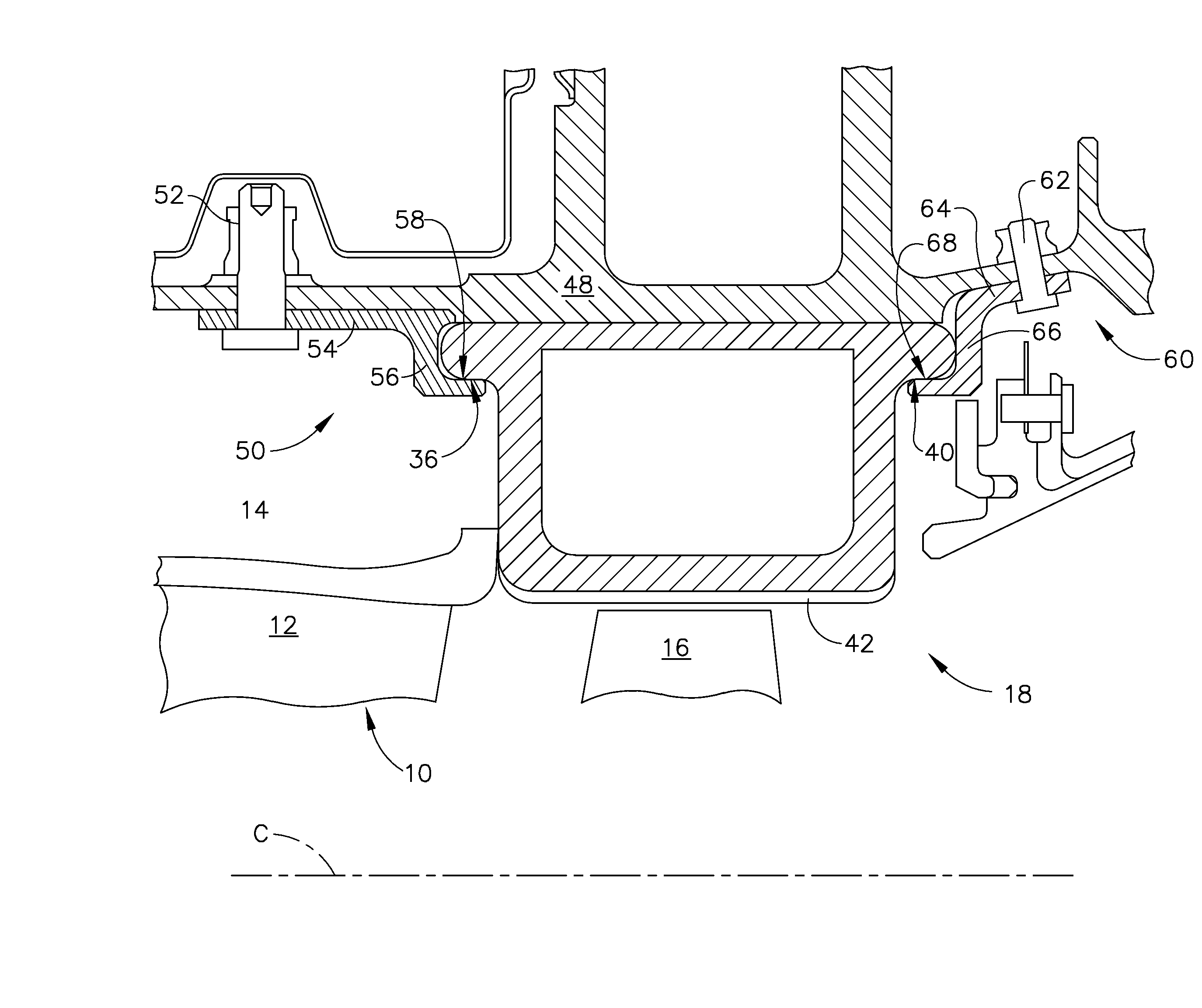
[0017]Referring to the drawings wherein identical reference numerals denote the same elements throughout the various views, FIG. 1 depicts a small portion of a high pressure turbine (“HPT”), which is part of a gas turbine engine of a known type. The function of the high pressure turbine is to extract energy from high-temperature, pressurized combustion gases from an upstream combustor (not shown) and to convert the energy to mechanical work, in a known manner. The high pressure turbine drives an upstream compressor (not shown) through a shaft so as to supply pressurized air to the combustor.

[0018]The principles described herein are equally applicable to turbofan, turbojet and turboshaft engines, as well as turbine engines used for other vehicles or in stationary applications. Furthermore, while a turbine nozzle is used as an example, the principles of the present invention are applicable to any low-ductility flowpath component which is at least partially exposed to a primary combust...


PUM


Abstract

A shroud apparatus for a gas turbine engine includes: a shroud segment comprising low-ductility material and having a cross-sectional shape defined by opposed forward and aft walls, and opposed inner and outer walls, the walls extending between opposed first and second end faces, wherein the inner wall defines an arcuate inner flowpath surface, wherein the shroud segment includes: a radially-inward facing chordal forward mounting surface; and a radially-inward facing chordal aft mounting surface; and an annular case surrounding the shroud segment, the case including: a radially-outward facing chordal forward bearing surface which engages the forward mounting surfaces; and a radially-outward facing chordal aft bearing surface which engages the aft mounting surface of the shroud segment.

Description

BACKGROUND OF THE INVENTION[0001]This invention relates generally to gas turbine engines, and more particularly to apparatus and methods for mounting shrouds made of a low-ductility material in the turbine sections of such engines.[0002]A typical gas turbine engine includes a turbomachinery core having a high pressure compressor, a combustor, and a high pressure turbine in serial flow relationship. The core is operable in a known manner to generate a primary gas flow. The high pressure turbine (also referred to as a gas generator turbine) includes one or more rotors which extract energy from the primary gas flow. Each rotor comprises an annular array of blades or buckets carried by a rotating disk. The flowpath through the rotor is defined in part by a shroud, which is a stationary structure which circumscribes the tips of the blades or buckets. These components operate in an extremely high temperature environment, and must be cooled by air flow to ensure adequate service life. Typi...

Claims


Application Information

Patent Timeline
Patent Type & Authority Applications(United States)
IPC IPC(8): F02C7/28F01D25/24F02C7/06
CPCF01D25/246F05D2250/75F05D2240/11F05D2300/6033
Inventor ALBERS, JOSEPH CHARLESMARUSKO, MARK WILLARD
Owner GENERAL ELECTRIC CO
Why Eureka
Try Eureka