Hose For A Piston-Chamber Combination

a technology of piston and chamfer, applied in the direction of pumps, mechanical devices, liquid fuel engines, etc., to achieve the effect of optimizing the function

Inactive Publication Date: 2013-01-03
NVB INT UK
View PDF9 Cites 1 Cited by
  • Summary
  • Abstract
  • Description
  • Claims
  • Application Information

AI Technical Summary

Benefits of technology

[0006]The object is to provide an optimalisation of the functionning of any

Problems solved by technology

Thus, it is unnessary, and when a universal bicycle p

Method used


Image

  • Hose For A Piston-Chamber Combination
  • Hose For A Piston-Chamber Combination
  • Hose For A Piston-Chamber Combination

Examples


Embodiment Construction

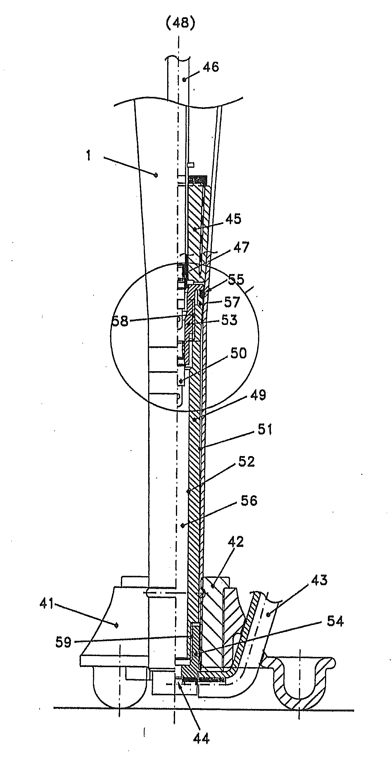
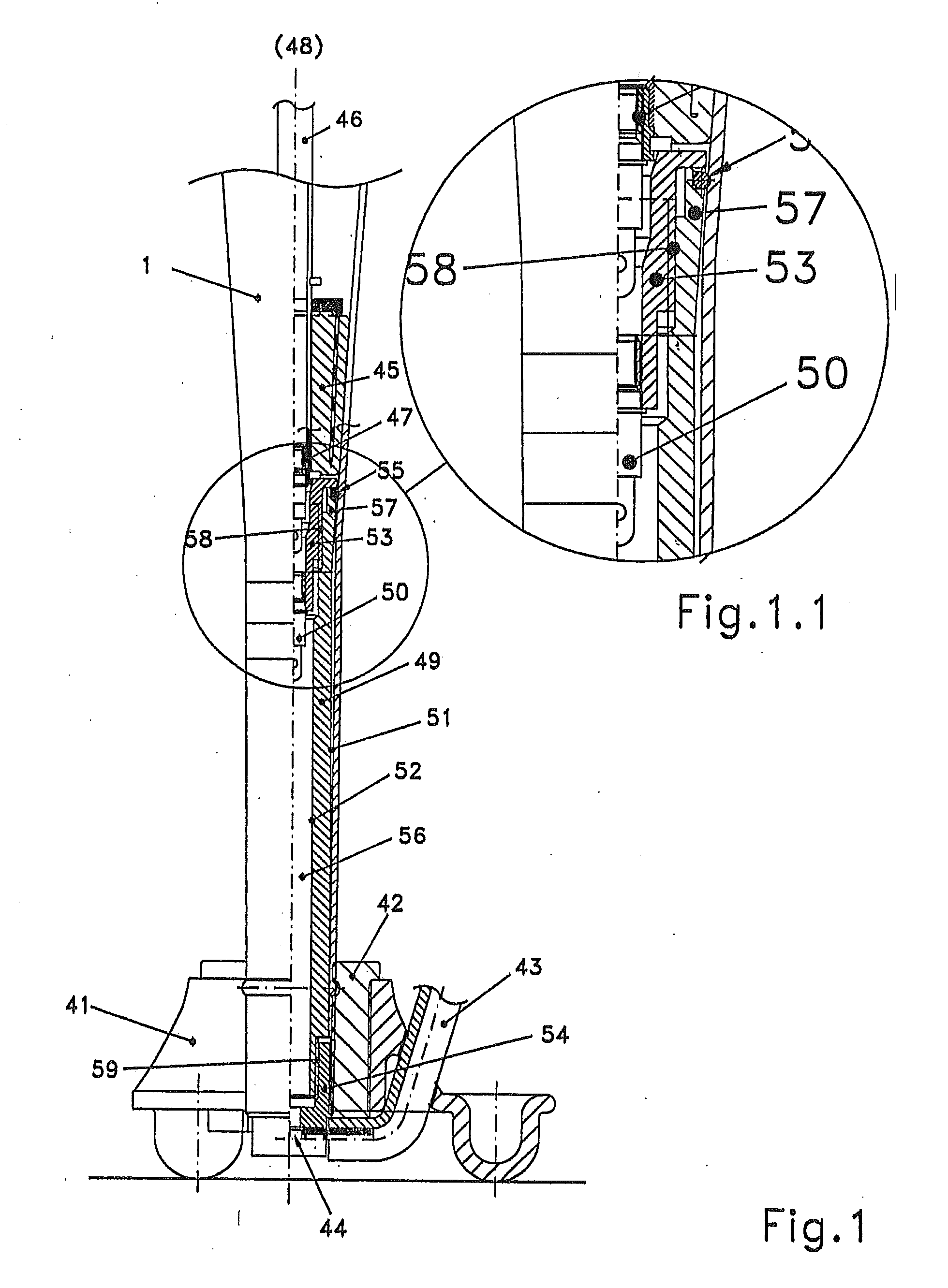
[0042]FIG. 1 shows a bottom part of a chamber of an advanced bicycle floor pump, where additionally the bottom part of the chamber is shown. A flexible manchet 42 assembles the chamber 1 on the foot 41. The hose 43, which is connected to the exit 44 of the pressure expansion vessel 49—this exit is without a check valve. The (schematically drawn) piston 45 is comprising a piston rod 46. At the bottom of the piston rod is a check valve 47 positioned, which is communicating with the external atmosphere (48), and is opening towards the chamber 1, so as to fill the chamber 1 when the piston 45 is moving from a second longitudinal position to a first longitudinal position. An expansion pressure vessel 49 with a chamber 56 is shown, comprising an inlet check valve 50, when open, the chamber 1 is communicating with the hose 43, through an exit 44. The cross-section of the external wall 51 of the expansion pressure vessel 49, with an inner wall 52. The expansion pressure vessel 49 is assembl...


PUM


Abstract

A piston-chamber combination comprising an elongate chamber which is bounded by an inner chamber wall, and comprising a piston in said chamber to be engagingly movable relative to said chamber wall at least between a first longitudinal position and a second longitudinal position of the chamber, said chamber having cross-sections of different cross-sectional areas and differing circumferential lengths at the first and second longitudinal positions, and at least substantially continuously different cross-sectional areas and circumferential lengths at intermediate longitudinal positions between the first and second longitudinal positions, the cross-sectional area and circumferential length at said second longitudinal position being smaller than the cross-sectional area and circumferential length at said first longitudinal position, said chamber is comprising an exit valve, which is communicating with a hose, which is communicating with a valve between the other end of said hose and an object to be inflated.
This is achieved by the size of the volume of said hose between said valves is variable.

Description

TECHNICAL FIELD[0001]A piston-chamber combination comprising an elongate chamber which is bounded by an inner chamber wall, and comprising a piston in said chamber to be engagingly movable relative to said chamber wall at least between a first position and a second position of the chamber,[0002]said chamber having cross-sections of different cross-sectional areas and differing circumferential lengths at the first and second positions, and at least substantially continuously different cross-sectional areas and circumferential lengths at intermediate positions between the first and second positions, the cross-sectional area and circumferential length at said second position being smaller than the cross-sectional area and circumferential length at said first position, said chamber is comprising an exit valve, which is communicating with a hose, which is communicating with a valve between the other end of said hose and an object to be inflated.BACKGROUND OF THE INVENTION[0003]This inven...

Claims


Application Information

Patent Timeline
IPC IPC(8): F04B41/02F04B45/06
CPCF04B45/06F04B53/162F04B53/14
Inventor VAN DER BLOM, NICOLAAS
Owner NVB INT UK
Why Eureka
Try Eureka