
Adhesive patching aid for microneedle adhesive skin patch

Active Publication Date: 2013-01-03
MEDRX CO LTD
View PDF5 Cites 13 Cited by
  • Summary
  • Abstract
  • Description
  • Claims
  • Application Information

AI Technical Summary

Benefits of technology

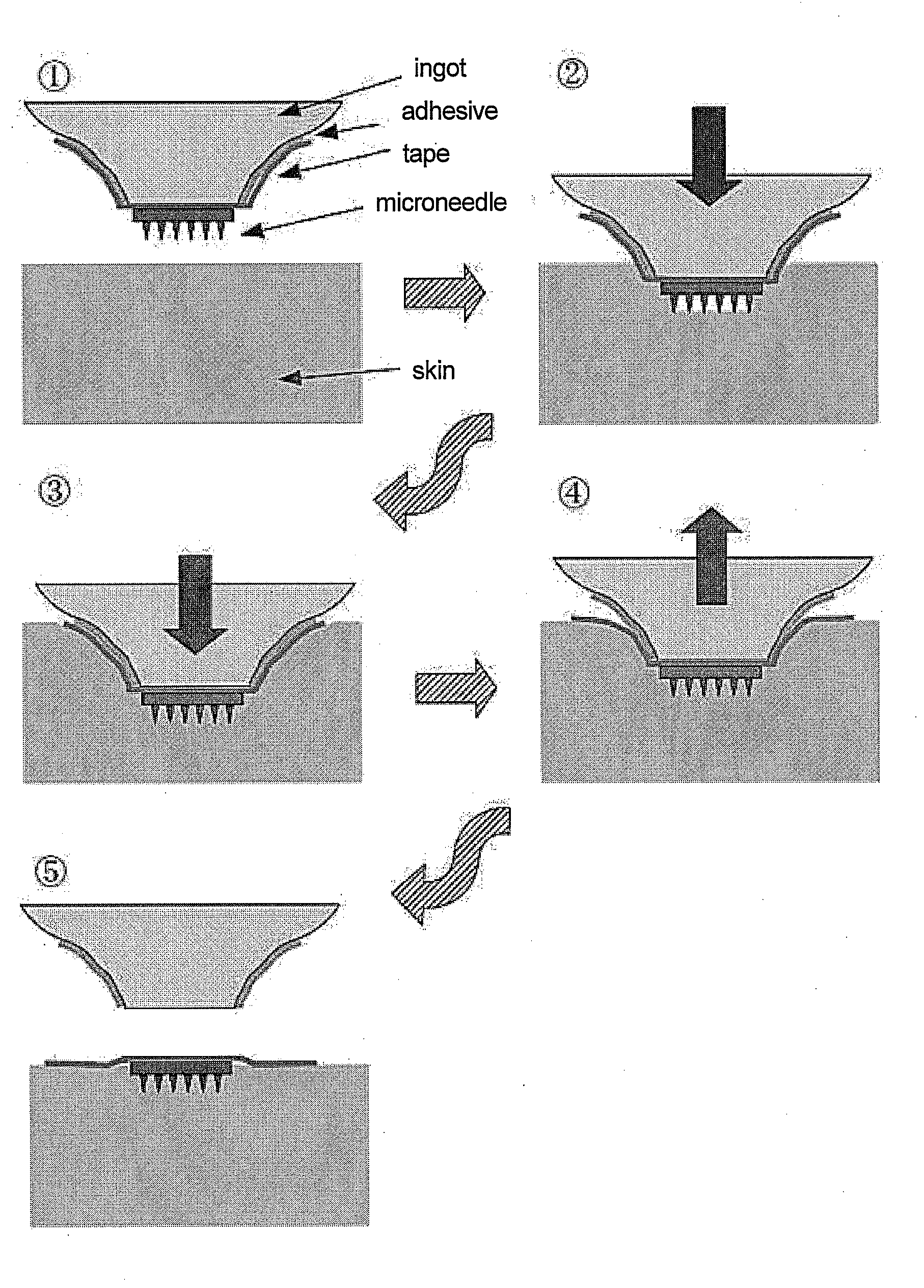
The present invention is about a tool that helps to hold a small needle and apply it to the skin. This tool has a base that can hold the needle and also has a tape to stick the needle to the skin. It is easy to use and can be designed to provide a comfortable and safe way to puncture the skin. This invention can make it easier for people to use the needle and apply it to their skin.

Problems solved by technology

However, when the material of the microneedle is a biodegradable resin and the angle of puncture relative to the skin is a little off perpendicular, the small needles of the microneedle break or bend easily, making it difficult to appropriately puncture the skin (patent document 1).
However, when a microneedle patch that can be fixed by adhesion to the skin with a tape was produced and actually used, adhesion to the skin was clarified to be insufficient during removal of the assisting tool of the patch since the microneedle is lifted up or separated from the skin.
To solve this, an adhesive having a weak adhesion power may be used between the applicator and the tape; however, a dilemma ultimately occurs in that it cannot stand distribution and the like.
However, the conventional method of simply pressing with finger(s) problematically cannot determine the stress.

Method used


Image

  • Adhesive patching aid for microneedle adhesive skin patch
  • Adhesive patching aid for microneedle adhesive skin patch
  • Adhesive patching aid for microneedle adhesive skin patch

Examples


experimental example 1

Puncture Test of Pin-Frog-Shaped Microneedle to the Skin

(1) Human Forearm Skin Model (A)

[0063]A 6 mm-thick sheet obtained by heat-melting SIS 30% and liquid paraffin 70% and molding the mixture was set, and a 9 mm-thick sheet obtained by heat-melting SIS 15% and liquid paraffin 85% and molding the mixture was laminated thereon to be 2 layers. On the substrate was placed the abdominal skin of a Wistar rat (male, 5 weeks) to give a human forearm skin model.

(2) Equipment

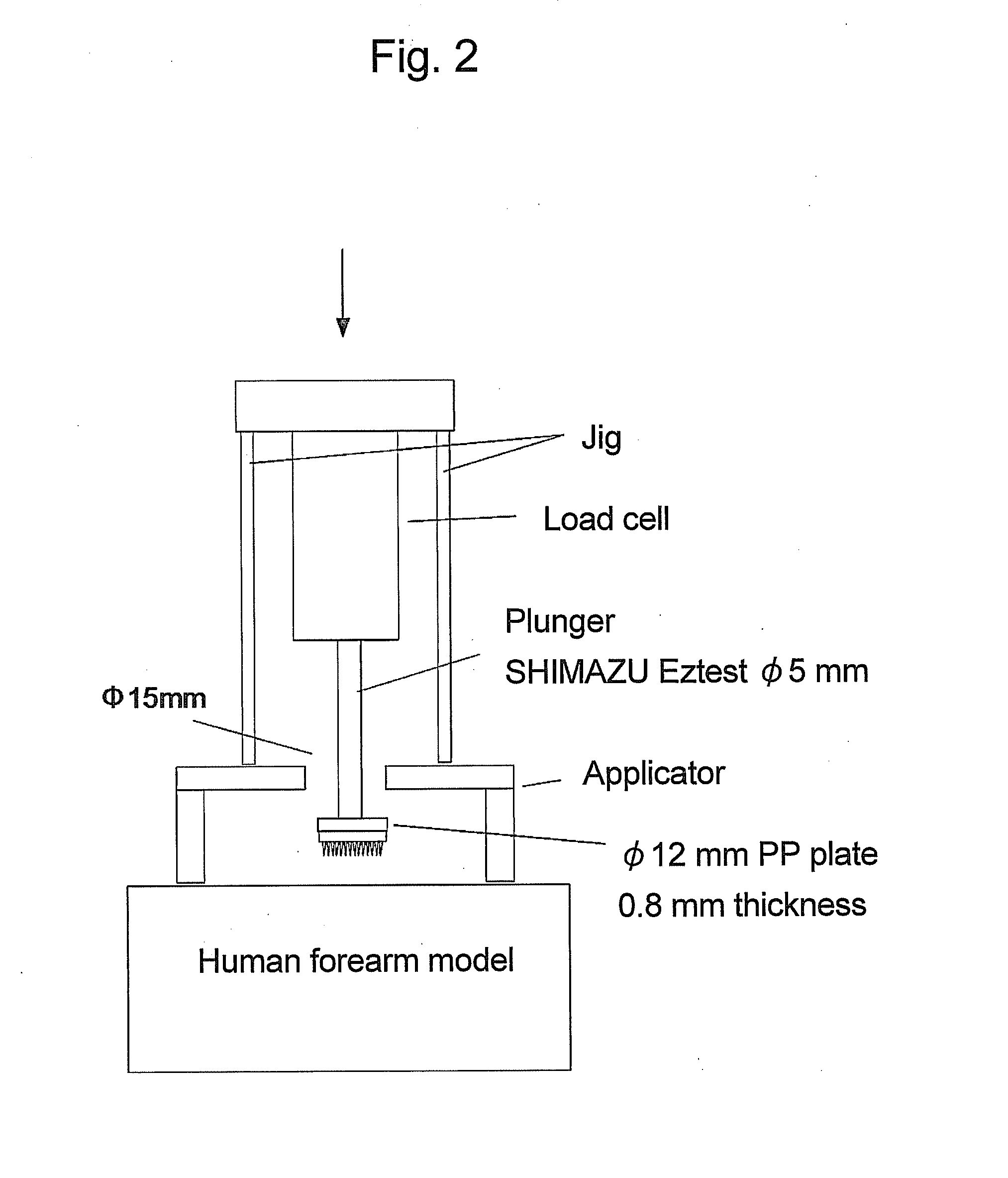
[0064]Using compact desktop type testing machine (Eztest) manufactured by Shimadzu Corporation, a plunger (Φ5 mm) was set on the load cell thereof, and a Φ12 mm polypropylene (PP) plate (0.8 mm thick) was further set on the tip thereof. A microneedle was placed on the tip of the PP plate.

(3) Pin-Frog-Shaped (Kenzan-Shaped) Microneedle

[0065]Using a resin sheet disk (circular plate) of polylactic acid (PLA) and polyglycolic acid (PGA) (Φ10 mm, 2 mm thick), a pin-frog-shaped microneedle was prepared according to a known me...

experimental example 2

Skin Puncture Test by Applicator Holding Pin-Frog-Shaped Microneedle

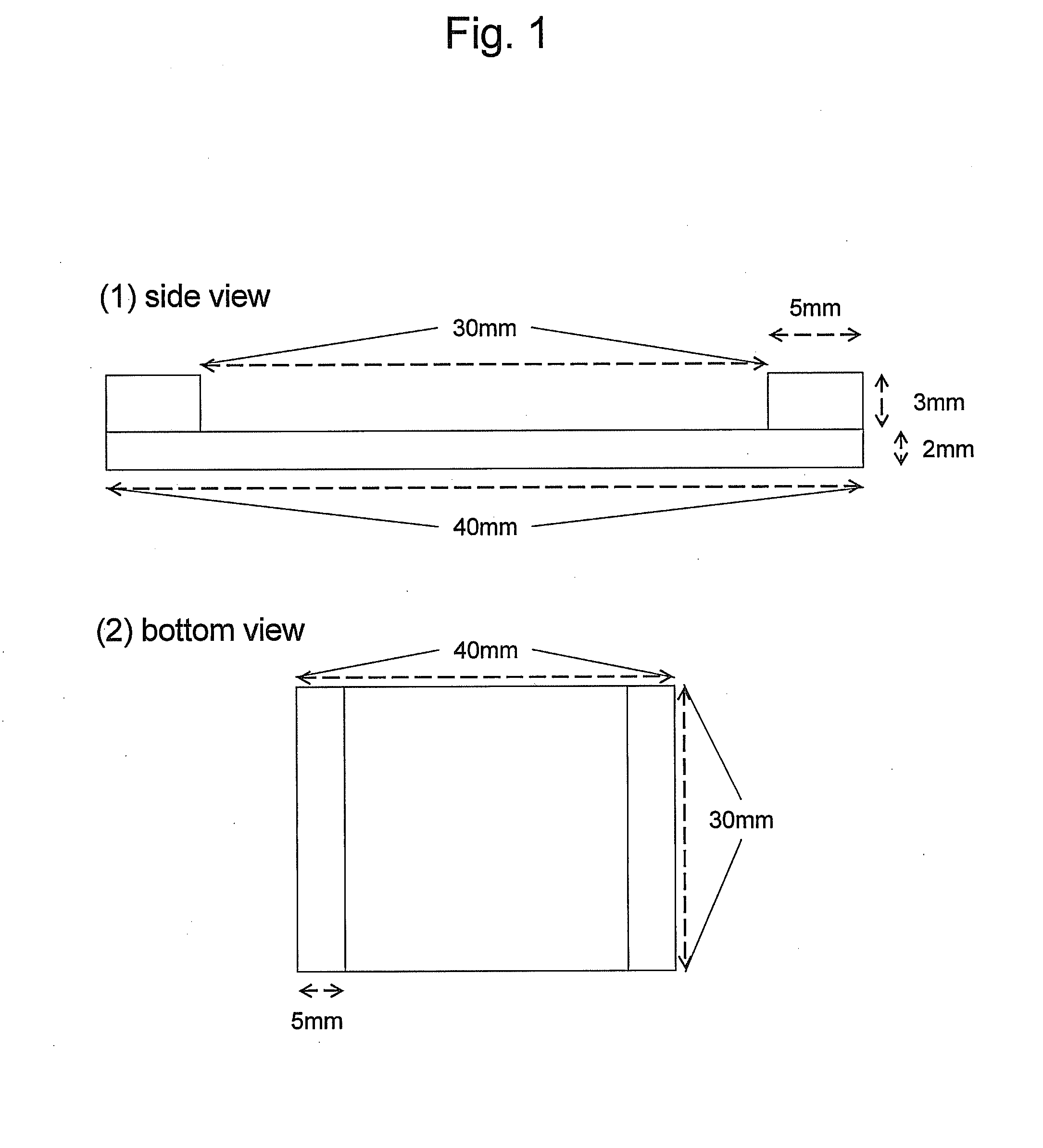
[0071]In the test of the above-mentioned Experimental Example 1, the microneedle was directly pressed against the skin model (A). From the previous findings, it is known that an applicator having a U-shaped cross-section as in FIG. 1 (a Japanese “geta”-shaped (a pair of side plates-shaped) applicator) provides a good puncture effect. Thus, changes in the puncturability of a pin-frog-shaped microneedle was examined by using such applicators (30×40 mm, various heights).

[0072]When the applicator shown in FIG. 1 is pressed against the skin, the skin free of pressing elevates perpendicularly. As a result, a microneedle can perpendicularly stick into the skin, affording very effective puncture.

[0073]To evaluate puncturability of a microneedle by using an applicator, the jig shown in FIG. 2 was prepared and the measurement was performed. A plunger (Φ5 mm) was set on the load cell of a compact desktop type testing machine (...

experimental example 4

Position of Supporting Base for Microneedle placed in Applicator and Change of Stress on Microneedle

[0095]As shown in the above-mentioned Experimental Example 3, the Japanese “geta”-shaped applicator elevates the skin surface more easily by pressing, which facilitates the microneedle to be pressed into the skin surface easily and deeply. In addition, protrusion of a supporting base (assisting tool) for microneedle in the Japanese “geta”-shaped applicator was considered to further facilitate the microneedle to be pressed into the skin surface when the skin elevates by pressing the applicator, thus increasing the stress applied to the microneedle. Thus, the jig of FIG. 5 was produced, and the relationship between the height of the supporting base (assisting tool) for the microneedle and the stress was evaluated. The distance of the skin surface and the tip of the microneedle was set to 1 mm as in Experimental Example 3. In FIG. 5, h shows the distance from the tip of the microneedle t...


PUM


Abstract

The invention provides an applicator that holds a microneedle to facilitate puncture of the skin and includes an assisting tool as a supporting base to set the microneedle and an adhesive sheet such as a tape and the like, on the side face of the assisting tool to enable close adhesion of the microneedle puncturing the skin.

Description

TECHNICAL FIELD[0001]The present invention relates to an assisting tool to accurately adhere a microneedle patch to the skin. More particularly, it relates to an embankment-shaped assisting tool which contains and holds a microneedle patch.BACKGROUND ART[0002]As a method for transdermal administration of a drug, application of a solution or ointment to the skin surface and a transdermal preparation in the form of a patch have conventionally been used. At present, however, in an attempt to increase the skin permeability of a drug, it has been tried to topically destroy the stratum corneum with small needles (microneedles or micropins) to forcedly deliver the drug to the dermal layer.[0003]As the material of a microneedle used to puncture the skin, metals, various resins and the like are used. To suppress disorders of the skin, biodegradable materials tend to be used often. However, when the material of the microneedle is a biodegradable resin and the angle of puncture relative to the...

Claims


Application Information

Patent Timeline
IPC IPC(8): A61M5/00
CPCA61M2025/0253A61M2037/0023A61M2037/0061A61M37/0015A61M2037/0046
Inventor KOBAYASHI, KATSUNORIHAMAMOTO, HIDETOSHI
Owner MEDRX CO LTD
Learn More