Cross link for spinal rod system

a cross-linking and spinal cord technology, applied in the field of cross-linking or connecting assemblies, can solve the problems of difficult manipulation of the clamp body length, difficulty in reaching and lying close to the spinal cord when implanted, and difficulty in adjusting the length of the clamp body, so as to facilitate the capture of spinal cords, further adjustability to positioning, and the effect of convenient device adjustmen

Active Publication Date: 2013-01-03
PIONEER SURGICAL TECH INC
View PDF8 Cites 25 Cited by
  • Summary
  • Abstract
  • Description
  • Claims
  • Application Information

AI Technical Summary

Benefits of technology

[0033]In another aspect of the invention, a plate member may include a track portion having guide tracks in which a pair of yoke members are slidably disposed. The sliding of the yoke members along the guide tracks allows the distance between the yoke members to be adjusted so that the yoke members may capture spinal rods adjusted to various distances from one another. In addition, the yokes may be rotatably and / or pivotably coupled to the guide tracks in a polyaxial manner that allows for rotation and / or pivoting in one or more planes in order to easily capture spinal rods so that they extend in a variety of different directions relative to the plate member, and specifically the track portion thereof. For instance, the yoke may be provided with a swiveling neck portion that is slidably received in the track member and allows the yoke member to swivel in one or more directions with respect to the track member.
[0034]In one preferred form, the yoke member may rotate about an axis of the neck portion so that a rod receiving channel or opening in the yoke may be positioned to face in various different directions with respect to the direction in which the yoke slides along the track member. In another preferred aspect of the invention, the neck member forms a ball-and-socket connection with the yoke member in order to allow pivoting of the yoke member in at least two planes in addition to rotation about an axis of the neck portion. Locking members may be provided in order to secure the spinal rods to the yoke members and to fix the position of the yoke members with respect to the track member and plate member. In one aspect of the invention, a single locking member associated with each yoke member fixes the position of a spinal rod with respect to the yoke member and fixes the pivoted and rotated position of the yoke member with respect to the neck portion and / or track member. In another aspect, a single locking member secures the position of two yoke members along the track member, such as by adjusting a clamp member that spans the length of the track member to exert frictional forces that prevent the yoke members from sliding relative to the track member. Alternatively, separate clamping members may be provided to prevent the sliding of each of the yoke members.
[0035]In another aspect, the rod receiving members may be coupled to the plate member by telescoping members that allow the distance of the rod receiving members from the plate member to be adjusted. This may include, for instance, a sleeve portion having an axial bore coupled to the plate member and a post member coupled to the rod receiving member, with the post member slidably received in the axial bore of the sleeve portion. Alternatively, the sleeve portion may be coupled to the rod receiving member and the post coupled to the plate member. The sleeve and post members also may be pivotably coupled to the plate member and / or rod receiving member in order to provide further adjustability to the positioning and orientation of the rod receiving members.
[0036]In another form, one or more rod receiving members may be coupled to a plate member by two or more ball-and-socket connections. A housing may be provided to connect one ball-and-socket connection to the next. In one preferred form, a single locking member is associated with each housing and is configured to lock the position of both ball-and-socket connections with respect to the housing. The ball-and-socket connections also may be pivotably and / or slidably connected to the plate member and / or the rod receiving member to provide further adjustability to the device.
[0037]The anchors used to secure the plate to the patient's skull may be expandable in order to increase their holding strength. For instance, the shank of the screw may be hollow and have one or more slits therein running parallel to the axis of the shank so that insertion of a pin or other member into the hollow shank causes the exterior of the shank to splay, expanding the width of the shank and applying additional lateral force against the bone adjacent to the shank exterior. This lateral force increases the load that may be placed on the screw in an axial direction before the screw is stripped out of the bone.

Problems solved by technology

When utilizing crosslinking or connecting devices to secure pedicle screws, a number of obstacles are commonly encountered.
However, providing multiple points of articulation presents further problems.
Additionally, many devices include a locking mechanism in the center of the crosslinking device to prevent translation, pivoting, and or rotation of the cross rod, which can be difficult for surgeons to reach and lies close to the spinal cord when implanted.
These features for adjusting the length of the clamp body are not easy to manipulate, and limit the positions at which the length may be locked.
Furthermore, the device does not allow for pivoting the clamp bodies relative to one another, making it difficult to use the device to connect spinal rod segments that are skewed relative to one another.
Thus, the device cannot easily be adjusted to accommodate bent or skewed spinal rods.
When spinal rods are mounted to the skull, however, long screws and large coupling assemblies cannot be mounted directly to the skull without undue risk of penetrating the brain encased therein.
Many coupling assemblies also would prove extremely and unduly cumbersome if mounted directly to the skull, and may even protrude significantly from the back of the head.
This bending of the rod can fatigue the rod material, and also makes it difficult to reposition the elements of the stabilization system.
Even attempts to provide occipital plate devices with adjustability in order to accommodate spinal rods of various orientations still generally require significant manipulation and bending of spinal rods before they can be secured to the plate structure.
While the bolt may be rotated to adjust the direction of the rod or cable, this adjustment affects only one plane, and does not allow for adjustment of the angle of the rod or cable with respect to the surface of the plate.
However, the device does not allow multiple types of movement to provide a highly articulated device.
Furthermore, the coupling heads are relatively bulky and still hold the spinal rods relatively parallel to the plate surface.

Method used


Image

  • Cross link for spinal rod system
  • Cross link for spinal rod system
  • Cross link for spinal rod system

Examples


Embodiment Construction

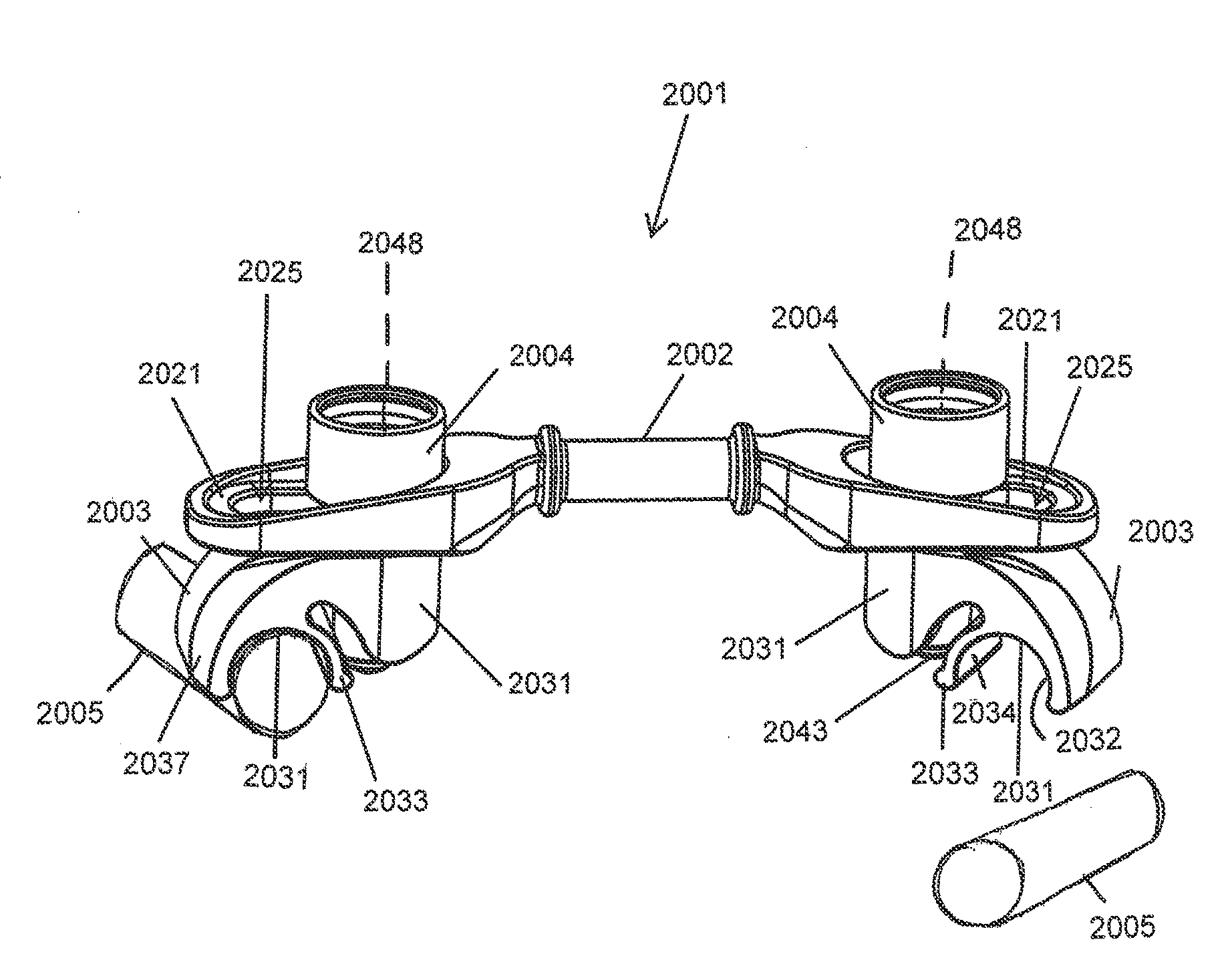
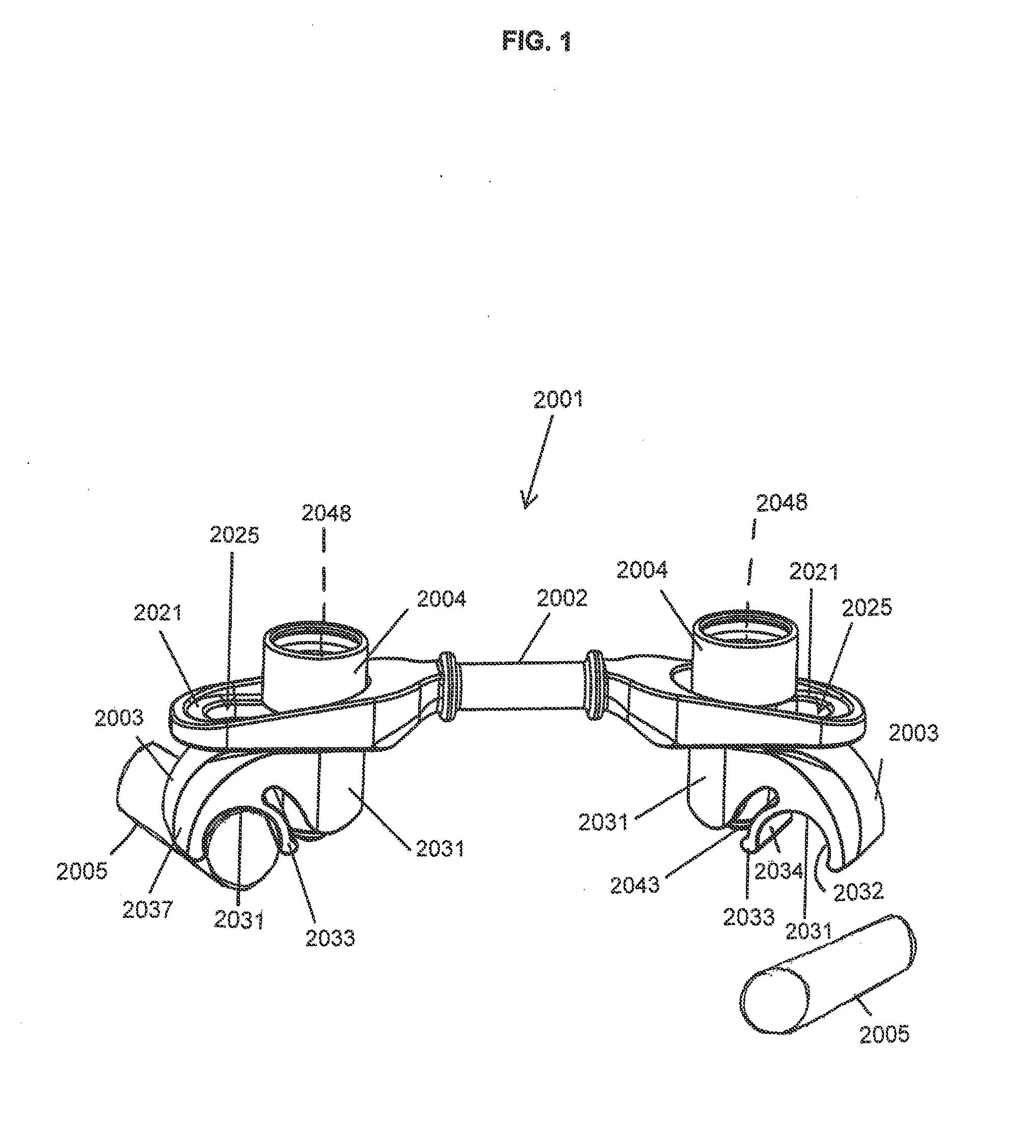
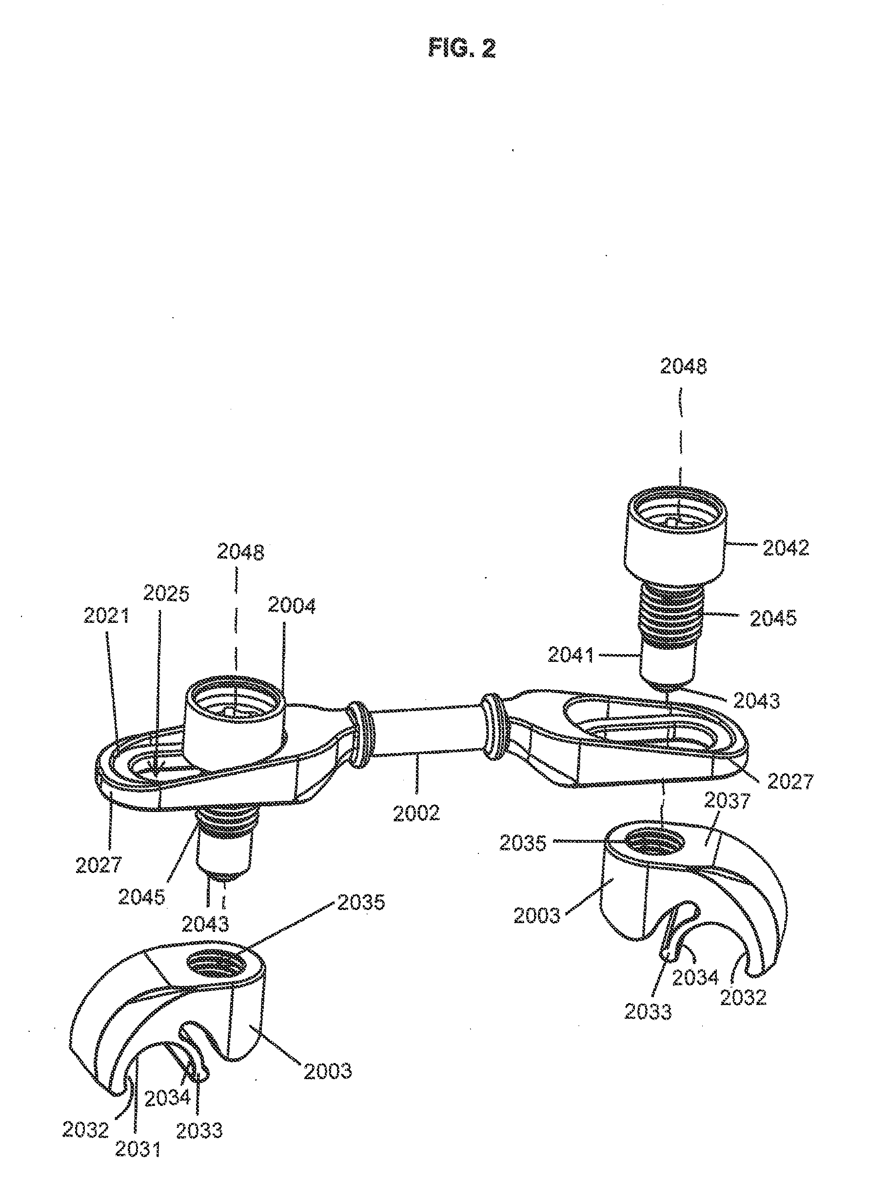
[0094]FIGS. 1-4 show a cross connector device 2001 that includes a bridge member 2002 and two separate clamping members 2003 for coupling the device to a pair of spinal rods. The illustrated clamp members 2003 each include a body portion 2037 and a clamping jaw portion 2033, with the clamping jaw portion 2033 formed adjacent an arcuate recess 2031 for receiving and holding in place a spinal rod 2005. As illustrated, each clamp member 2003 is a unitary construct and the body portion 2037 and the clamping jaw portion 2003 have arcuate surface portions 2032 and 2034 which cooperate to form the arcuate recess 2031, with clamping jaw 2033 being a relatively thin flexible portion that is integral to the clamp body 2037. Alternatively, the jaw portion may be a separate member that is pivotable with respect to the clamp body 2037.

[0095]The clamping members 2003 are independently coupled to the central elongate bridge member 2002 by locking actuators 2004, which pass through elongate adjustm...


PUM


Abstract

A device for connecting two spinal rods is provided. In one form, the device includes two clamping devices for receiving and locking to spinal rods and a central bridge or plate member that couples the clamping devices. In one aspect, the clamping devices are unitary members with deflectable jaw portions that snap-fit and then locked by operation of actuators. In another aspect, one or both of the clamping devices are adjustably coupled to the central bridge or plate member to allow at least translation and pivoting or rotation of the clamping devices relative to a central axis of the elongate bridge member. The clamping devices may be coupled to the bridge or plate member with the same locking actuator that causes clamping of the clamp device so that the positions of the clamp device and the spinal rod are locked into place by manipulation of only a single locking actuator.

Description

CROSS-REFERENCE TO RELATED APPLICATIONS[0001]This application claims benefit of U.S. Provisional Application No. 61 / 532,355 filed Sep. 8, 2011, which is incorporated by reference in its entirety. This application is also a continuation-in-part of U.S. patent application Ser. No. 12 / 983,207, filed Dec. 31, 2010, which claims benefit of U.S. Provisional Application No. 61 / 298,488, filed Jan. 26, 2010, which are both hereby incorporated herein by reference in their entirety.FIELD OF THE INVENTION[0002]The invention relates to a crosslink or connecting assembly and method to secure multiple spinal rods in relation to each other and, in particular, to a connecting assembly disposed transversely between two spinal rods that has moveable components for rotating, pivoting, and extending portions of the connecting device, as well as actuating members for locking the moveable components in place.BACKGROUND OF THE INVENTION[0003]In surgical procedures involving the spine, it is common to secur...

Claims


Application Information

Patent Timeline
Patent Type & Authority Applications(United States)
IPC IPC(8): A61B17/70
CPCA61B17/705A61B17/7052A61B17/8695A61B17/8685A61B17/7055A61B17/7059
Inventor ROBINSON, DANIEL RAEGEPHART, MATTHEW P.SULLIVAN, JOHN
Owner PIONEER SURGICAL TECH INC
Why Eureka
Try Eureka