
Method and Apparatus for Testing Attachment Joints

a technology for fixing joints and apparatus, applied in the field of test fixture apparatus, can solve the problem of reducing the design/build cycle time of corrugated beams, and achieve the effect of reducing the test cycle tim

Inactive Publication Date: 2013-01-10
THE BOEING CO
View PDF3 Cites 3 Cited by
  • Summary
  • Abstract
  • Description
  • Claims
  • Application Information

AI Technical Summary

Benefits of technology

The patent describes a reusable test fixture that can be used to simulate the loads on a floor beam in an aircraft. This fixture can be quickly attached to the beam and can produce loads that closely match those of a full length floor beam. The fixture can be used to generate design capacity curves for multi-axis applied loads and varying floor beam geometries. This helps streamline the stress analysis process and reduces the time needed to design and build corrugated floor beams.

Problems solved by technology

The availability of these design capability curves may streamline the stress analysis process and may reduce the design / build cycle times for corrugated beams.

Method used


Image

  • Method and Apparatus for Testing Attachment Joints
  • Method and Apparatus for Testing Attachment Joints
  • Method and Apparatus for Testing Attachment Joints

Examples


Embodiment Construction

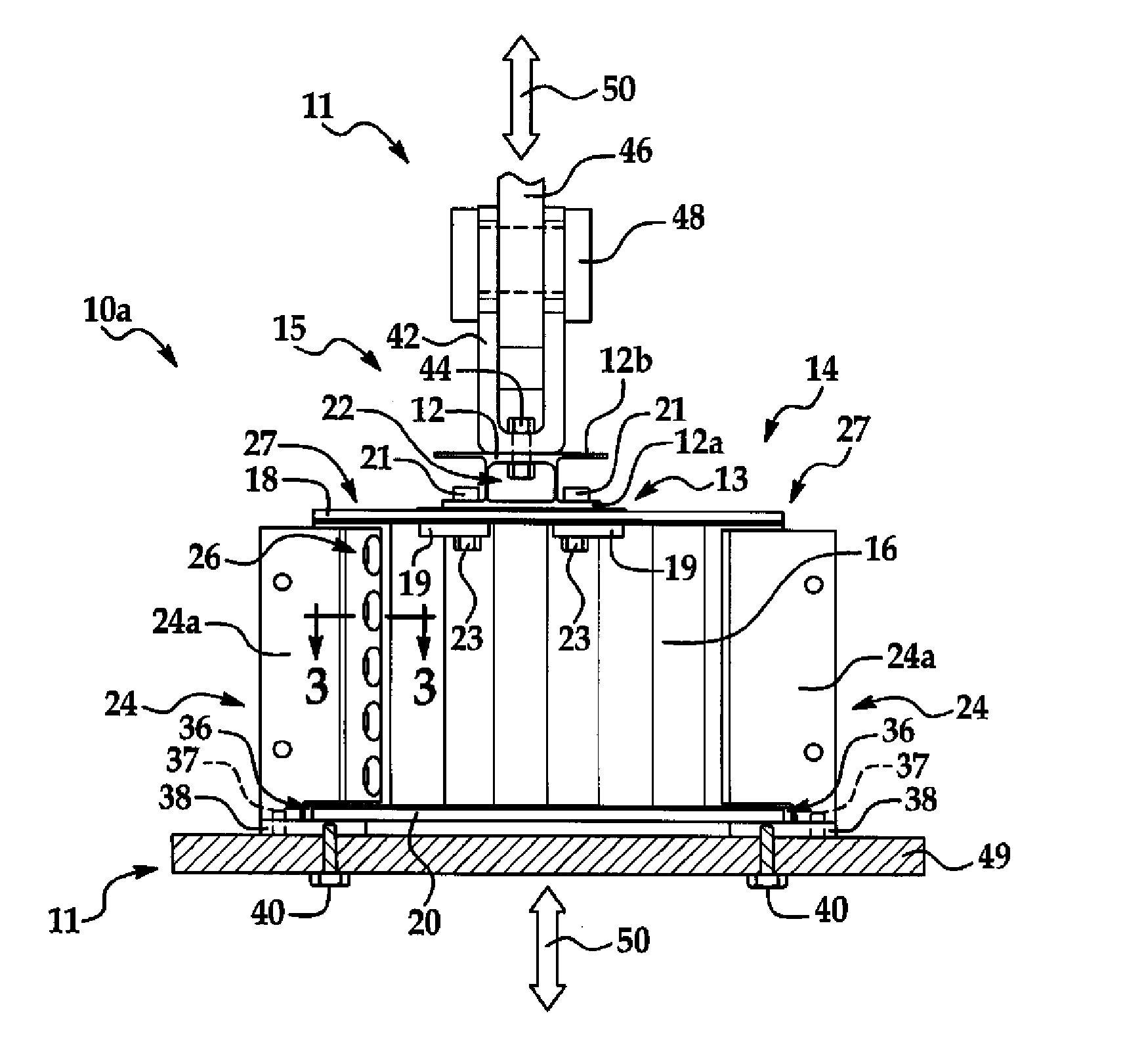
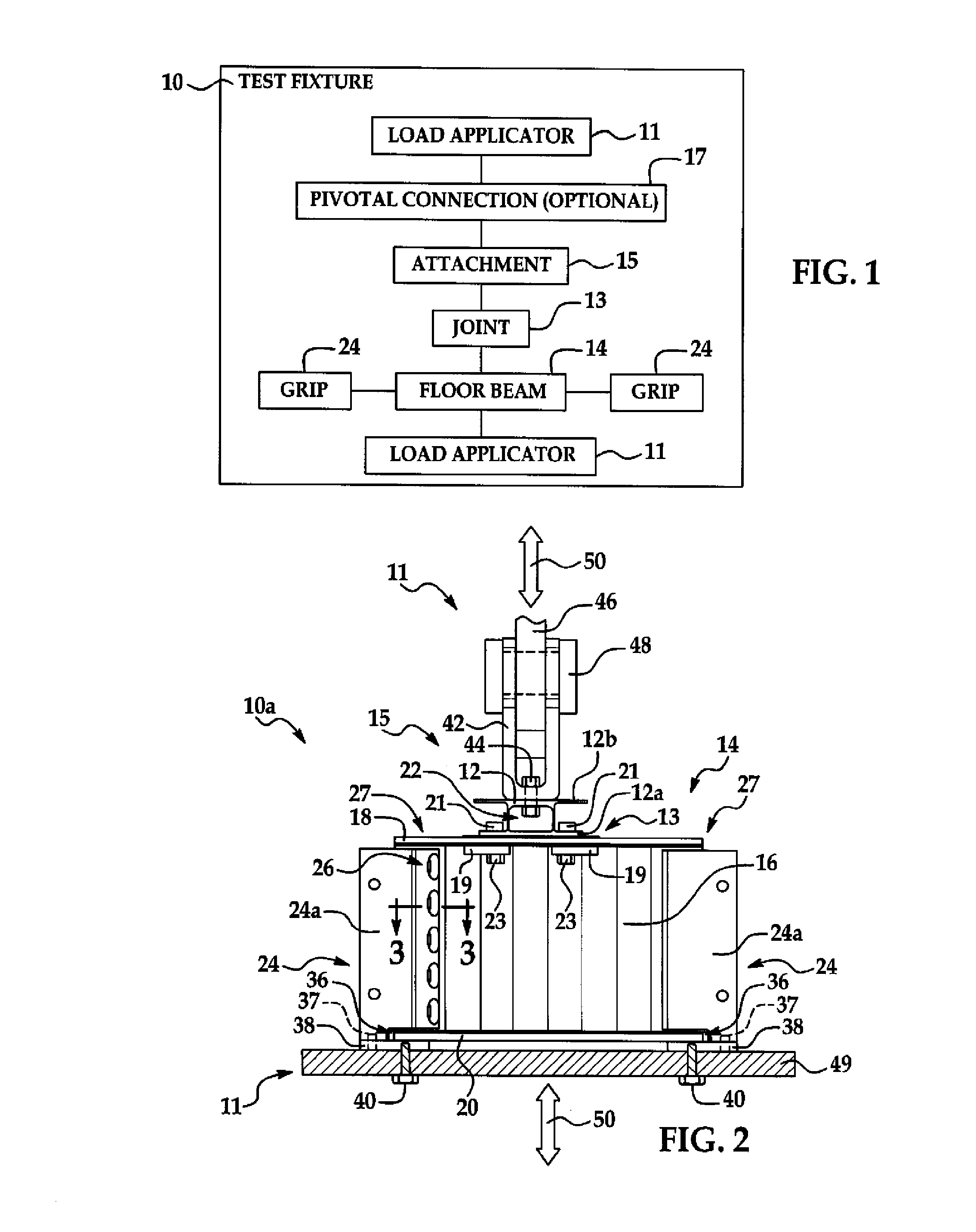
[0024]Referring first to FIG. 1, a reusable test fixture 10 includes a load applicator 11 for applying shear loads and / or bending moments through a joint 13 between an attachment 15 to a floor beam 14. The floor beam 14 is held by a pair of grips 24, and the load may be applied through a pivotal connection 17 between the load applicator and the attachment 15. As will be discussed in more detail below, the attachment 15 may comprise any of a variety of structural members, fixtures or hardware, and the floor beam 14 may comprise only a short section of a full length floor beam that is used as a test specimen to determine the performance of the joint 13 between the floor beam 14 and the attachment 15.

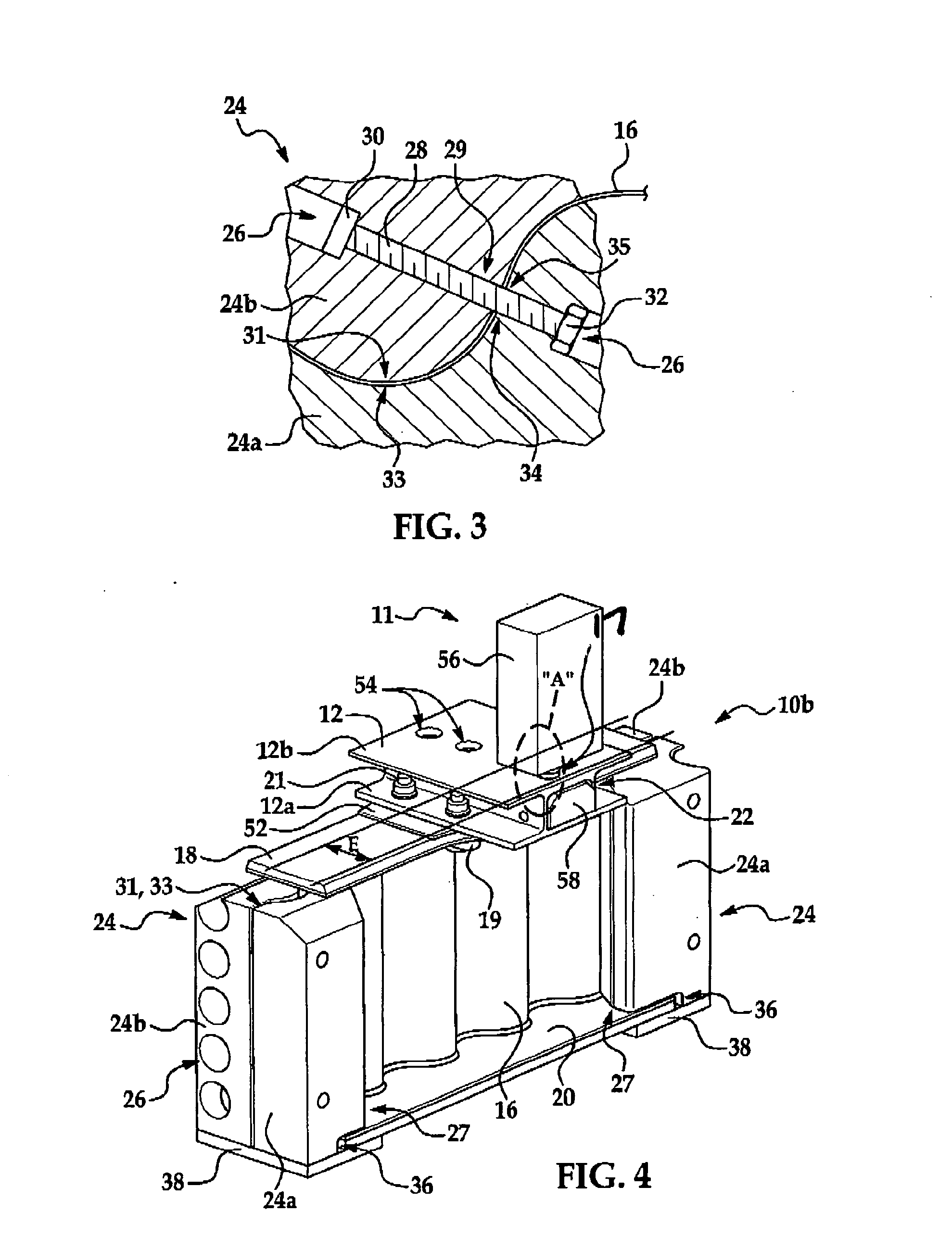
[0025]Referring now to FIGS. 2 and 3, in one embodiment, a test fixture 10a broadly includes a load applicator 11 and a pair of grips 24a for testing a joint 13 between an attachment 15 in the form of a seat track 12 and a floor beam 14. Although a seat track 12 is illustrated in FIG. 2, i...


PUM

PropertyMeasurementUnit
lengthaaaaaaaaaa
strengthaaaaaaaaaa
shear loadaaaaaaaaaa

Abstract

Apparatus tests the performance of joints between an attachment and a beam having a pair of caps connected by a corrugated web. The apparatus includes first and second grips contoured to the shape of a portion of the corrugated web for gripping the web. A force applicator coupled with the attachment and the grips applies force to the beam through the joint.

Description

TECHNICAL FIELD[0001]This disclosure generally relates to test fixtures, and deals more particularly with a test fixture apparatus and related method for testing the performance of a joint between an attachment and a beam.BACKGROUND[0002]It is sometimes necessary to test the performance of attachment joints. For example, in the aircraft industry, a variety of attachments such as, without limitation, stanchions, seats, partitions and other fixtures may be attached to either the top or the bottom of beams that support cargo or cabin floors. These attachments may be connected to the floor beam by various types of attachment hardware, such as, without limitation, seat tracks which are used to mount passenger seats on the floor beams. The floor beams may comprise a pair of caps connected by a web that may be either substantially straight and flat along the length of the beam, or contain non-flat and / or undulating sections. Beams having non-flat and / or undulating webs may also be known as...

Claims


Application Information

Patent Timeline
Patent Type & Authority Applications(United States)
IPC IPC(8): G01N3/24
CPCG01N3/04G01N2203/0264G01N19/04G01N3/24
Inventor FOLTZ, GREGORY A.KAJITA, KIRK B.
Owner THE BOEING CO
Learn More