Test contactor for electrical testing of electronic components

a contactor and electronic component technology, applied in the direction of electrical testing, measurement devices, instruments, etc., can solve the problems of slowing down the testing cycle and relatively large travel stroke, and achieve the effect of reducing the testing cycle tim

Active Publication Date: 2014-02-20
ASMPT SINGAPORE PTE LTD
View PDF4 Cites 0 Cited by
  • Summary
  • Abstract
  • Description
  • Claims
  • Application Information

AI Technical Summary

Benefits of technology

[0009]Thus, the invention seeks to provide an electrical test contactor system which serves to reduce the testing cycle time by avoiding the disadvantages associated with the aforesaid prior art.

Problems solved by technology

A disadvantage of adopting this approach is that, in addition to positioning the electronic component next to the contact strips during testing, the electronic component has to be driven by a certain distance towards the contact strips at every testing cycle until the contact resistance between the electrical leads of the component and the contact strips is low enough to create good contact therebetween.
The additional time taken to drive the electronic component further by a predetermined distance during the electrical test of every component significantly slows down the testing cycle.
However, this approach still requires a relatively large travel stroke in order to create enough contact force to ensure good contact and to reduce contact resistance during electrical testing.

Method used


Image

  • Test contactor for electrical testing of electronic components
  • Test contactor for electrical testing of electronic components
  • Test contactor for electrical testing of electronic components

Examples


Embodiment Construction

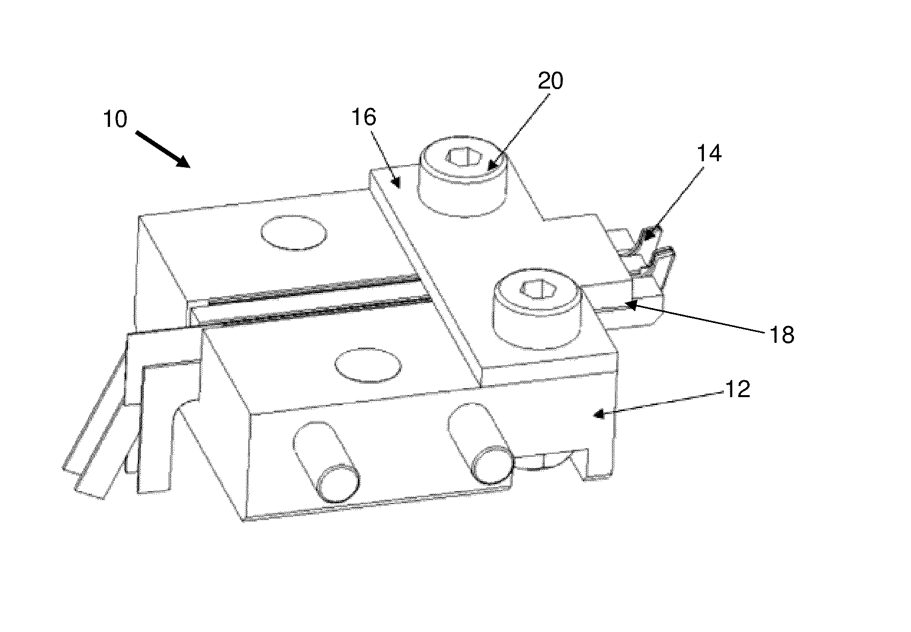
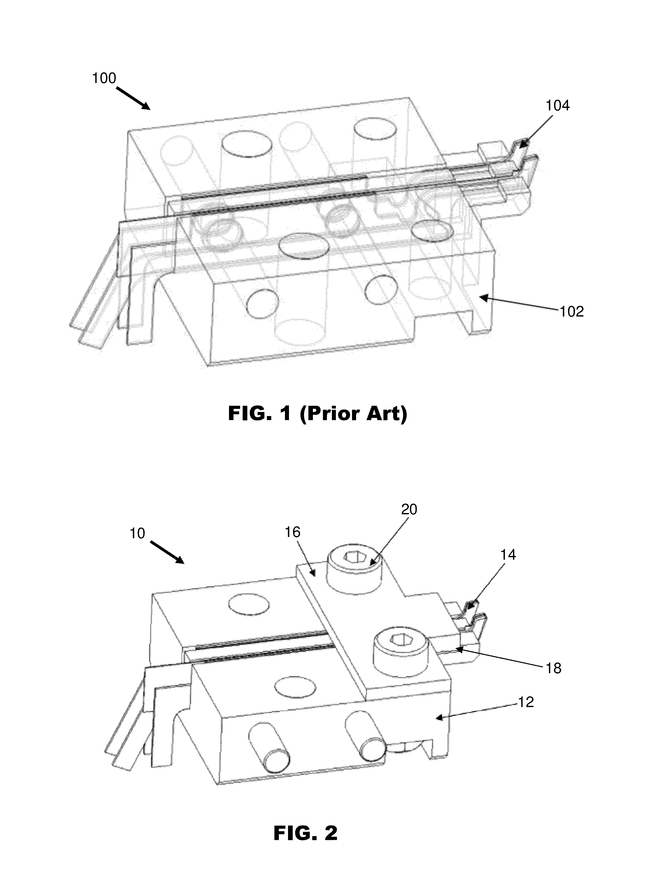
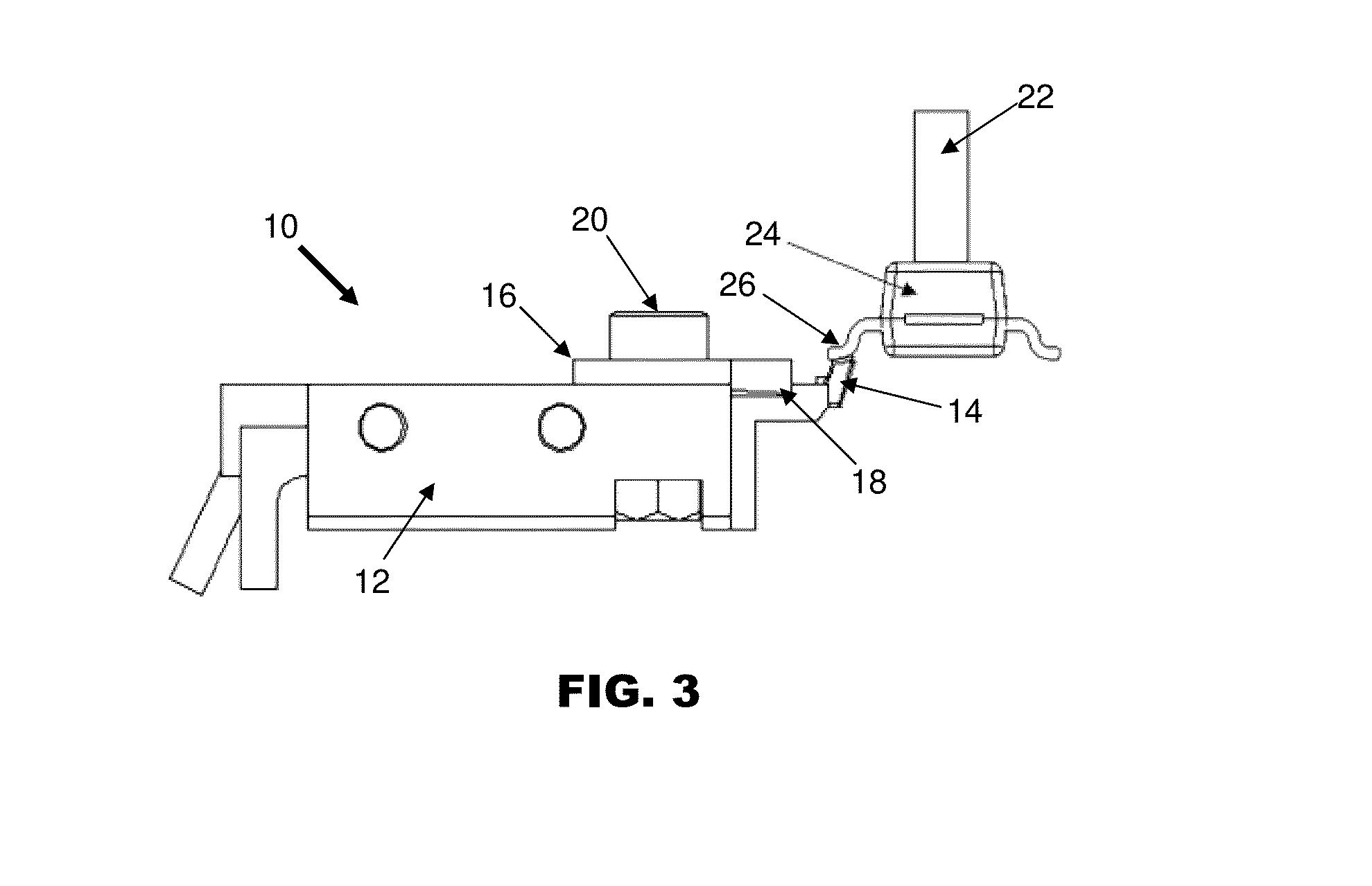
[0016]FIG. 2 is an isometric view of contact strips 14 mounted on a mounting block 12 in a test contactor 10 according to the preferred embodiment of the invention. As in a conventional test contactor 100, the contact strips 14 comprise elongated strips of electrically-conductive material which are centrally attached and mounted to a mounting block 12. The plurality of contact strips 14 are arranged and configured such that electrical leads of an electronic component are operative to press against and bend the contact strips 14 in a biasing direction to ensure good contact between the electrical leads and the contact strips during testing of the electronic component. When the contact strips 14 are not contacted with the electrical leads of the electronic component, they are generally horizontal.

[0017]Additionally, a preload block 16 is located on the mounting block 12 on top of the contact strips 14. Preferably, the preload block 16 is detachably mounted on the mounting block 12. Th...


PUM


Abstract

A testing apparatus for electronic components comprises a mounting block and a plurality of contact strips arranged on the mounting block. The contact strips are configured such that electrical leads of an electronic component are operative to press against and bend the contact strips in a biasing direction to ensure good contact between the electrical leads and the contact strips during testing of the electronic component. Further, a preload block located on the mounting block is operative to contact and apply a pre-stress force onto the contact strips in the biasing direction prior to contact between the electrical leads and the contact strips.

Description

FIELD OF THE INVENTION[0001]The invention relates to a tester for testing electronic components, and in particular to an electrical contactor for such tester.BACKGROUND AND PRIOR ART[0002]Conventionally, a contacting device comprises a plurality of contact strips, and a mounting block for mounting the contact strips. In order to perform testing on an electronic component, the component being tested is positioned onto the contact strips so that electrical leads of the component make electrical contact with the contact strips. Upon electrical contact being made, the electronic component is then generally driven further in the direction of the contact strips to bend the contact strips and to ensure that there is good contact between the electrical leads of the component and the contact strips.[0003]This is because whether the electrical contact is good enough to ensure testing reliability is determined by the contact resistance between the electrical leads and the contact strips. For t...

Claims


Application Information

Patent Timeline
Patent Type & Authority Applications(United States)
IPC IPC(8): G01R1/073
CPCG01R1/06772G01R1/0416G01R1/07342
Inventor SIU, HING SUENCHEUNG, YU SZECHENG, CHI WAHLAU, KAI FUNG
Owner ASMPT SINGAPORE PTE LTD
Why Eureka
Try Eureka