Vessel comprising a stowable magnus-effect rotor

a rotor and magnus technology, applied in the field of hulls, can solve the problems of undisturbed deck operations, reduced deck space used during and after folding of the rotor or telescopic retraction of the rotor, etc., and achieve the effect of optimizing the space available for deck operations, reducing the risk of damage, and improving the stability of the rotor

Active Publication Date: 2013-01-10
WINKLER JORN PAUL
View PDF2 Cites 5 Cited by
  • Summary
  • Abstract
  • Description
  • Claims
  • Application Information

AI Technical Summary

Benefits of technology

[0016]Additionally, it is advantageous to provide a vessel, wherein the movable segments comprise side segments which are, at least partially, sideways retractable with respect to the movable segments. Thus, the movable segments can be folded in any direction without having to deal with any disadvantages from the overlapping of segments.
[0017]Also, a vessel can advantageously be provided, wherein the movable segments comprise diafragmatically rotatable segments, the segments being rotatable with respect to a central part of the end plate. Thus, the segments can advantageously be stored under the surface of the central part, further optimizing the space available for deck operations after or during folding of the rotor. Also, after unfolding of the rotor the segments can be extended advantageously by making use of centrifugal forces resulting from the spinning up of the rotor for operations, therefore skipping over the need for an additional extension mechanism for the segments.
[0018]Furthermore, a vessel can advantageously be provided, wherein the movability of the segments is effectuated by a driving means connected to the movable segments. The driving means allow for accurate controllability of the positioning of the segments.
[0019]Additionally, a vessel can be provided, wherein the driving means comprise a hydraulics system for moving the segments. The driving means can advantageously be provided with a hydraulics system for moving the segments. A hydraulics system provides the advantage of being relatively reliable, especially in conditions at sea, where high moisture and salt levels can interfere with moving parts.
[0020]It would also be advantageous to provide a vessel, where the driving means comprising a pneumatics system for moving the segments. A pneumatics system basically has the same advantage as a hydraulics system, i.e. being relatively reliable in demanding conditions, such as at sea.
[0021]Furthermore, it is advantageous to provide a vessel, wherein the driving means comprise an electrical system for moving the segments. An electrical system has as an advantage that the positioning of the segments can be effectuated even more accurately, and the overall size of the electrical driving means in terms of utilized space is relatively small.

Problems solved by technology

Therefore, the deck space used during and after folding of the rotor or telescopic retraction of the rotor is decreased and deck operations can proceed in an undisturbed manner.

Method used


Image

  • Vessel comprising a stowable magnus-effect rotor
  • Vessel comprising a stowable magnus-effect rotor
  • Vessel comprising a stowable magnus-effect rotor

Examples


Embodiment Construction

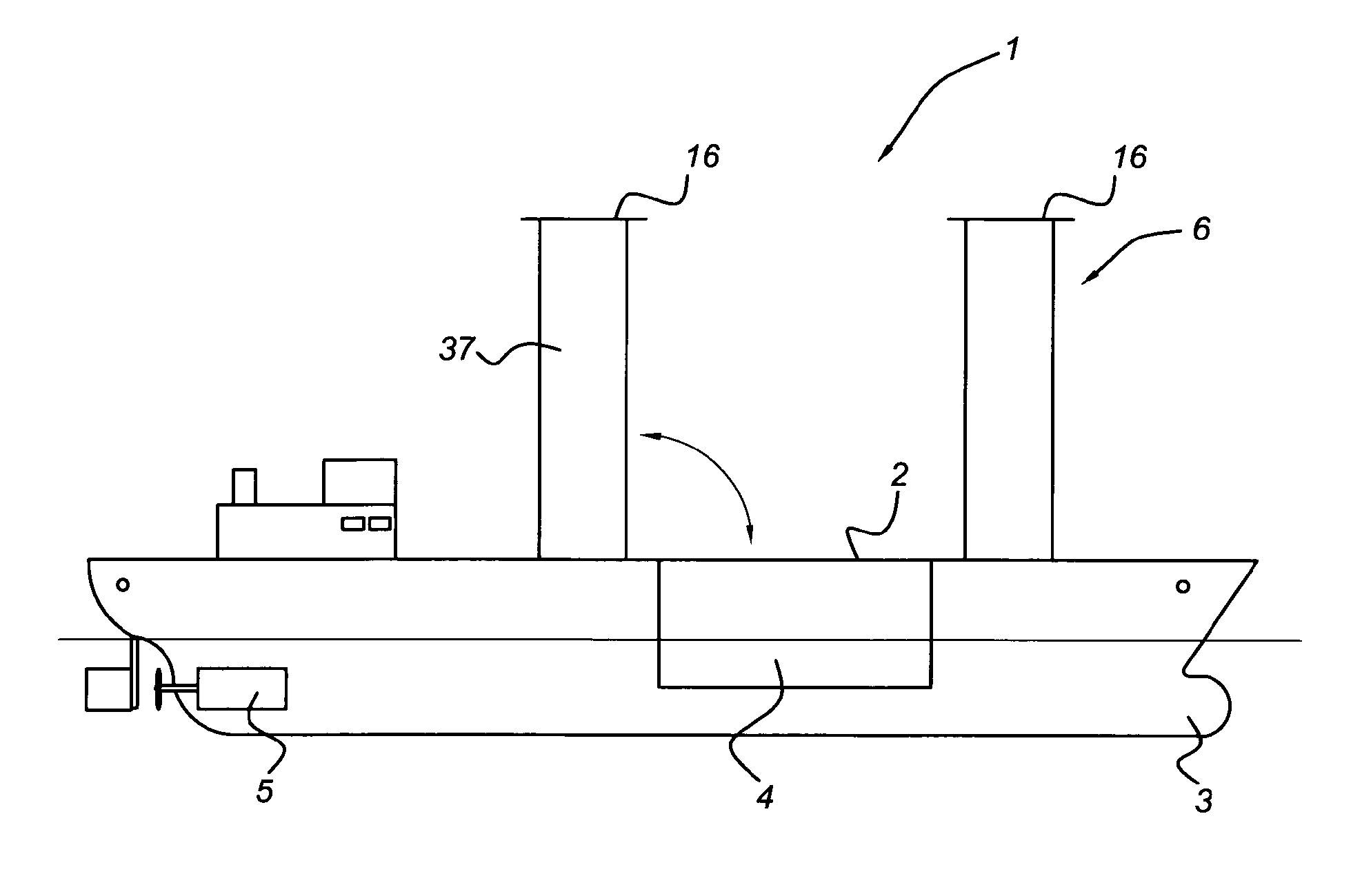
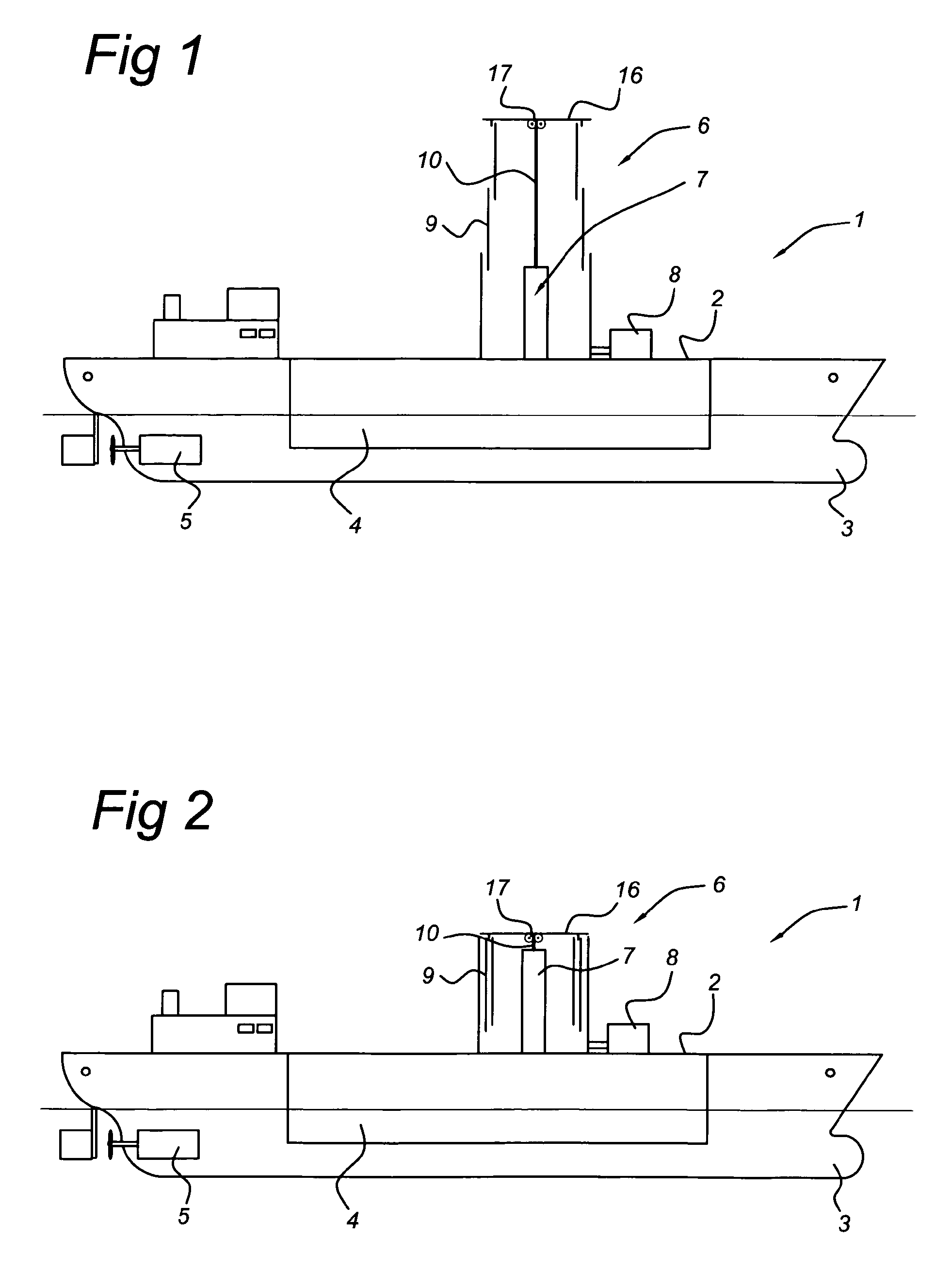
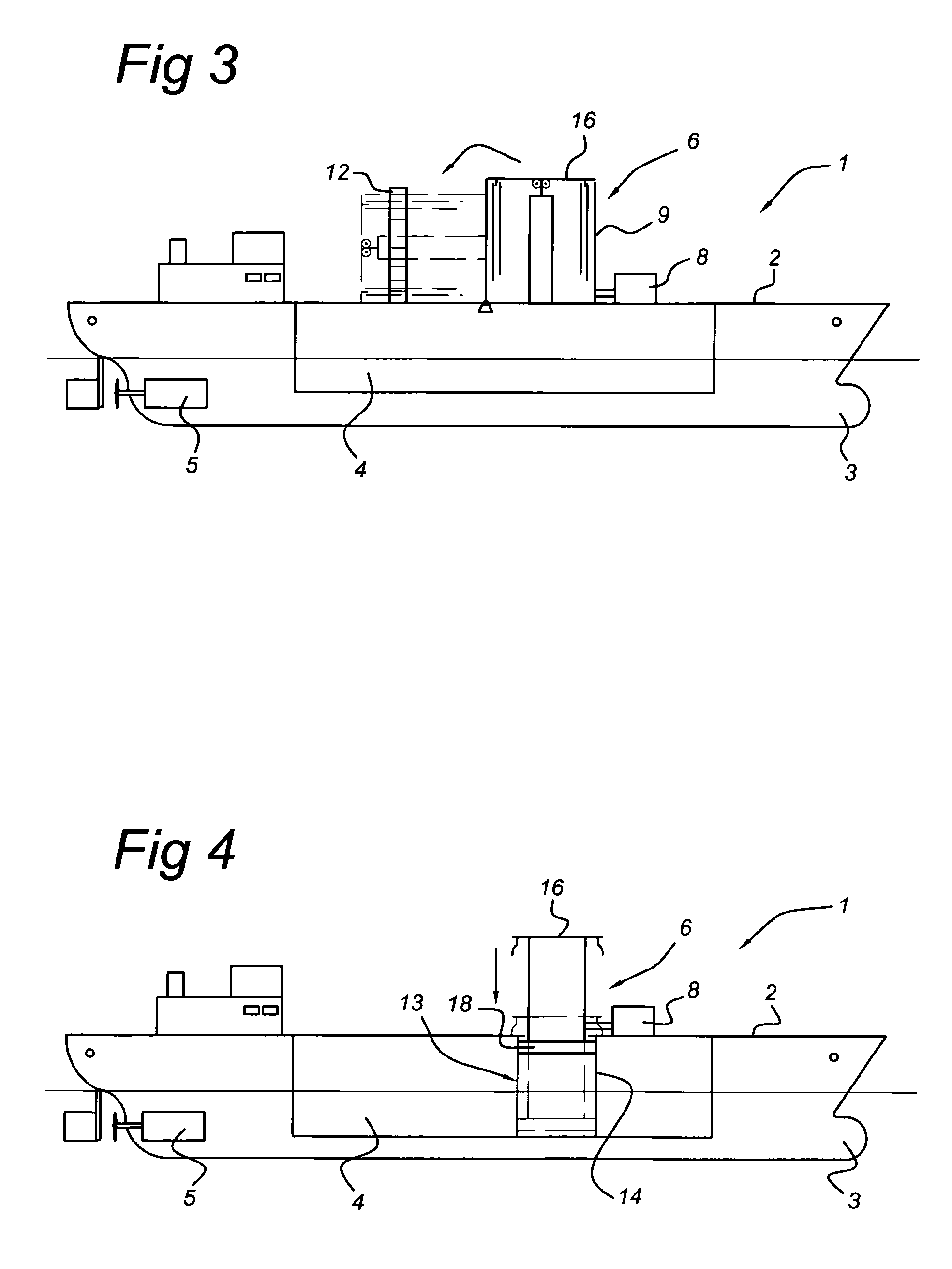
[0065]FIG. 1 shows a schematic side view of a vessel equipped with a telescopically retractable rotor in an extended, operational state, according to an embodiment of the invention; the vessel 1 is provided with a cargo compartment 4 for storing cargo. The vessel 1 is also equipped with a propulsion system 5 for propelling the vessel 1. The hull 3 comprises the forementioned cargo compartment 4. The upper part of the hull 3 is formed by the deck 2. The cylindrical rotor 6 is placed on the deck 2. Also situated on the deck 2 is a rotational drive means 8 for rotating or spinning the rotor 6 to a desired rotational speed. The rotor 6 itself comprises several tubular segments 9. The tubular segments 9 are telescopically fitted into each other, with their longitudinal axes essentially in line with each other and their outer surfaces partly overlapping. Along the longitudinal axis of the rotor 6 a displacement member 7 is placed for extending the rotor 6 to its operational state, and for...


PUM


Abstract

A vessel includes a hull and a deck, a substantially cylindrical rotor having a peripheral wall rotatable with respect to the deck around a longitudinal center line, the rotor being at a lower end connected to the deck and including an upper end plate, the rotor being mounted on the deck in such a manner that in an operational state the rotor is substantially vertically oriented and in an inoperational state the upper end plate is situated in the vicinity of the deck, the end plate extending transversely to the longitudinal center line, wherein the end plate is provided with movable edge segments that in the operational state of the rotor extend radially outwardly from the peripheral wall to an extended position and in the inoperational state of the rotor are moved to a retracted position that is situated closer to the peripheral wall than the extended position.

Description

FIELD OF THE INVENTION [0001]The invention relates to a vessel comprising a hull and a deck, a substantially cylindrical rotor having a peripheral wall rotatable with respect to the deck around a longitudinal center line, the rotor being at a lower end connected to the deck and comprising an upper end plate, the rotor being mounted on the deck in such a manner that in an operational state the rotor is substantially vertically oriented and in an inoperational state the upper end plate is situated in the vicinity of the deck, wherein the end plate extends transversely to the longitudinal center line.BACKGROUND OF THE INVENTION[0002]Such a Magnus-effect rotor is known from U.S. Pat. No. 4,602,584. It has long been known that a circular cylinder rotating about its longitudinal axis is capable of producing a lift force when placed in an air stream flowing perpendicular to the longitudinal axis of the cylinder, quite similar to the lift force produced by a wing when placed in a laminar ai...

Claims


Application Information

Patent Timeline
Patent Type & Authority Applications(United States)
IPC IPC(8): B63H9/02
CPCY02T70/58B63H9/02Y02T70/5236
Inventor WINKLER, JORN PAUL
Owner WINKLER JORN PAUL
Why Eureka
Try Eureka