Wellbore plug and method

a wellbore and plug technology, applied in the direction of wellbore/well accessories, fluid removal, sealing/packing, etc., can solve the problems of substantially higher setting force, inducing tension and compressive stresses in the mandrel, and affecting the operation of the plug, so as to achieve the effect of eliminating tension stress

Inactive Publication Date: 2013-01-10
BOOTH JOHN F
View PDF6 Cites 87 Cited by
  • Summary
  • Abstract
  • Description
  • Claims
  • Application Information

AI Technical Summary

Benefits of technology

[0015]The present invention provides a drillable, downhole wellbore tool with mandrels made from easy-to-drill materials such as concrete. The present invention provides a tool design and setting method that substantially reduces if not eliminates the tension stresses imposed on the plug's mandrel during setting and when in use which, in turn, permits the wellbore plug's mandrel to be made of concrete or other easy-to-drill materials.
[0016]According to a feature of the present invention, a double-slip configuration plug design, setting tool and setting method are provided which uses a setting rod connected to the mandrel near the bottom end of the tool (the end opposite from the setting the tool). During the setting method, force is applied to the mandrel through the setting rod which substantially eliminates tension in the mandrel during the setting procedures. When this invention is embodied in a frac plug, the top of the mandrel is closed off by a flapper valve or ball drop check valve which eliminates tension forces on the mandrel when pressure is applied across the tool. When the invention is embodied in a packer or bridge plug embodiment, the mandrel is closed off at both the top and bottom by check valves to eliminate tension in the mandrel. These designs substantially eliminate the application of tension and shear forces to the mandrel during the setting process and during use. This permits mandrels to be made with smaller cross section designs and from materials that need not have relatively high strengths in tension. Examples of suitable mandrel materials include cementitious materials, such as concrete, plastics, sintered materials and the like.

Problems solved by technology

While conventional plugs are in use or held in place, differential pressures across the plug can induce tension and compressive stresses in the mandrel.
Plugs of the double-slip configuration have a disadvantage of requiring substantially higher setting forces than the other configurations of plugs, and therefore the plugs' components, in particular the mandrel, experience substantially higher internal tension stresses during setting.
While mandrels made from high-strength plastic materials are easier to drill out than mandrels made from metallic materials, problems have been experienced in the drilling out of these mandrels.

Method used


Image

  • Wellbore plug and method
  • Wellbore plug and method
  • Wellbore plug and method

Examples


Embodiment Construction

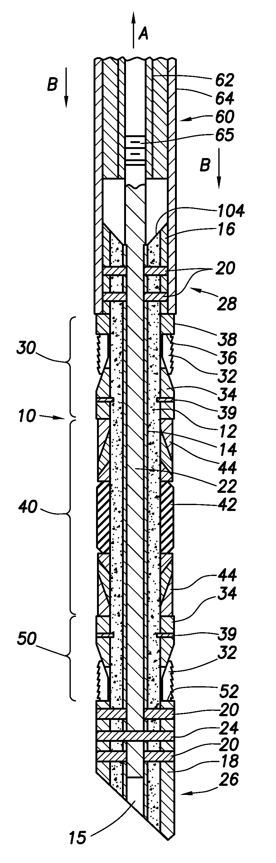
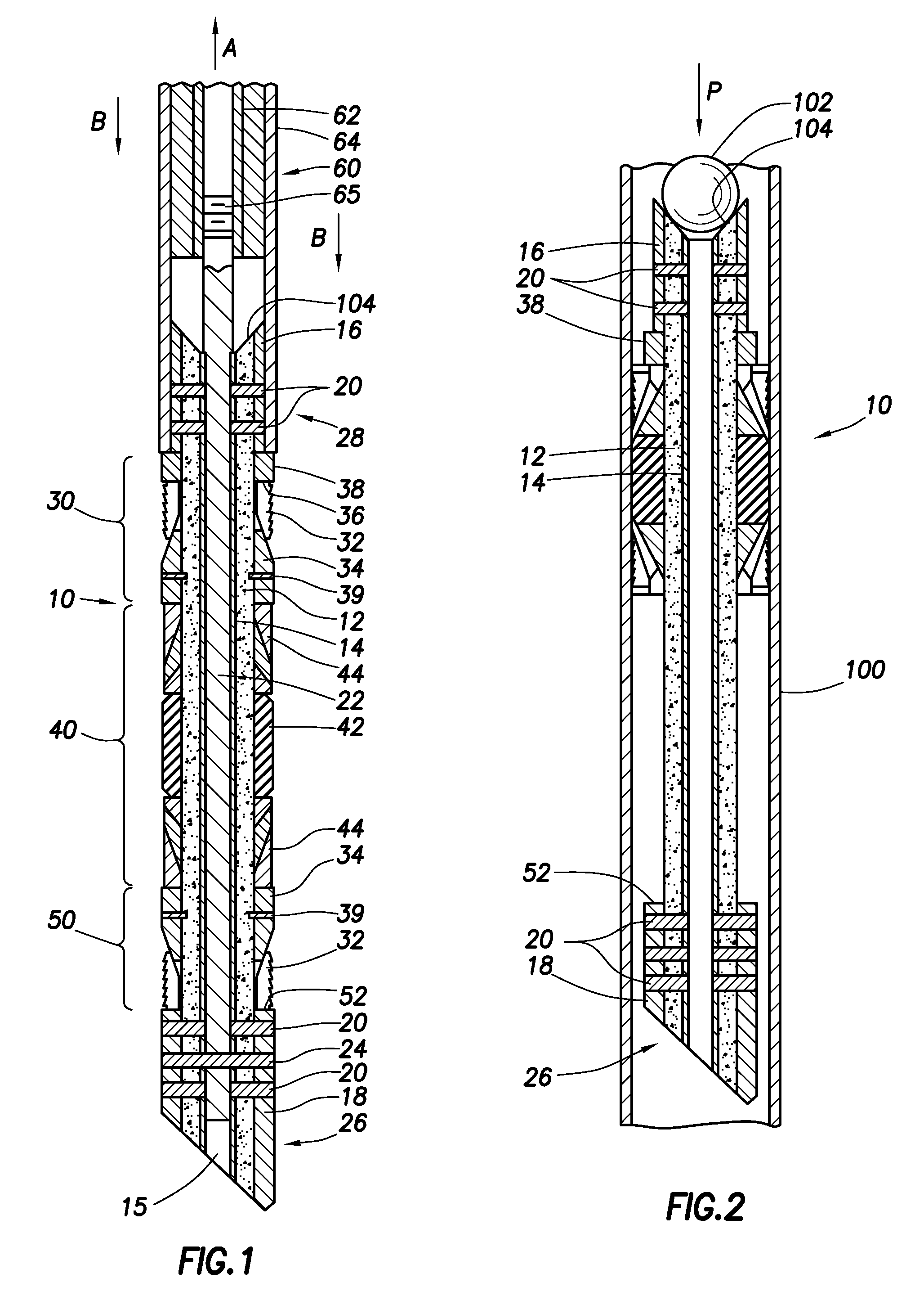
[0023]Referring now to the drawings wherein like reference characters designate like or corresponding parts throughout the several views, there is shown in FIG. 1 an embodiment of an improved double-slip type wellbore plug assembly 10 according to the present inventions. The plug embodiment selected for use in describing the present inventions comprises what is known in the industry as a frac plug. As will be described in detail, the frac plug, once set in the wellbore, permits hydrocarbon production flow along the wellbore upward through the plug, while preventing frac fluids pumped into the well to flow in a downward or downhole direction. For purposes of description, plug assembly 10 is illustrated in the figures with the upper end of the plug 28 orientated toward the top of the drawing page and lower end of the plug 26 toward the bottom of the page. It is to be understood that the embodiment selected for use as an example is not intended to limit the inventions to the selected c...


PUM


Abstract

Disclosed is a wellbore plug having a design that allows the mandrel of the plug to be made of concrete or other easy-to-drill materials. Disclosed is a wellbore plug assembly with slip and packing assemblies configured to hold the plug in place during setting and use without tensioning the mandrel, thereby allowing the mandrel to be made from easily drillable material, such as concrete.

Description

CROSS REFERENCE TO RELATED APPLICATIONS[0001]This application claims priority from U.S. Provisional Patent Application No. 61 / 505,195, filed Jul. 7, 2011, entitled “Wellbore Plug and Method,” which is hereby incorporated by reference in its entity.BACKGROUNDTechnical Field[0002]These inventions relate generally to methods and apparatus for drilling and completing subterranean wells and, more particularly, drillable wellbore plugs designed to have mandrels made of concrete or other easy-to-drill materials or shapes.[0003]In the drilling of wells and in mining applications, it is necessary to temporarily isolate sections of a wellbore. For example, a common method sets a plurality of plugs to isolate and successively treat sections of the wellbore. As used herein, the term “plug” is used to refer to bridge plugs, packers, frac plugs, cementing shoes, squeeze plugs and the like utilized at subterranean wellbore locations. This isolation method has been accomplished using “drillable wel...

Claims


Application Information

Patent Timeline
Patent Type & Authority Applications(United States)
IPC IPC(8): E21B33/13E21B33/12
CPCE21B33/128E21B33/1216
Inventor BOOTH, JOHN F.
Owner BOOTH JOHN F
Why Eureka
Try Eureka