Electronic Circuits and Techniques for Improving a Short Duty Cycle Behavior of a DC-DC Converter Driving a Load

a technology of dc-dc converter and short duty cycle, applied in the direction of electric variable regulation, process and machine control, instruments, etc., can solve the problems of unnecessarily high power dissipation of switching regulator, dc-dc converter without feedback control, dc-dc converters are unable to achieve very short duty cycle times when switched on and off, etc., to achieve a wide dynamic range of power

Active Publication Date: 2013-01-10
ALLEGRO MICROSYSTEMS INC
View PDF4 Cites 57 Cited by
  • Summary
  • Abstract
  • Description
  • Claims
  • Application Information

AI Technical Summary

Benefits of technology

[0017]The present invention provides circuits and techniques that can achieve a wide dynamic range of power provided by a DC-DC converter to a load in a feedback loop arrangement, while allowing a DC-DC converter to maintain proper operation and proper voltage regulation.

Problems solved by technology

While it is possible to provide a fixed voltage switching regulator that can supply enough voltage for all possible series strings of LEDs, such a switching regulator would generate unnecessarily high power dissipation when driving strings of series connected LEDs having less voltage drop.
If the DC-DC converter is left on when the current through the load is switched off, the DC-DC converter would lack feedback control and the output voltage of the DC-DC converter could move to a different voltage, which is undesirable.
For reasons described below, DC-DC converters are unable to achieve very short on times when switched on and off.
In view of the above, it should be recognized that, when a short on time is desired to achieve a wide brightness dynamic range, the DC-DC converter may not behave properly in short duty cycle operation and fluctuations of the output voltage of the DC-DC converter may result, which may result in undesirable fluctuation (flicker) in the brightness of the LEDS.

Method used


Image

  • Electronic Circuits and Techniques for Improving a Short Duty Cycle Behavior of a DC-DC Converter Driving a Load
  • Electronic Circuits and Techniques for Improving a Short Duty Cycle Behavior of a DC-DC Converter Driving a Load
  • Electronic Circuits and Techniques for Improving a Short Duty Cycle Behavior of a DC-DC Converter Driving a Load

Examples


Embodiment Construction

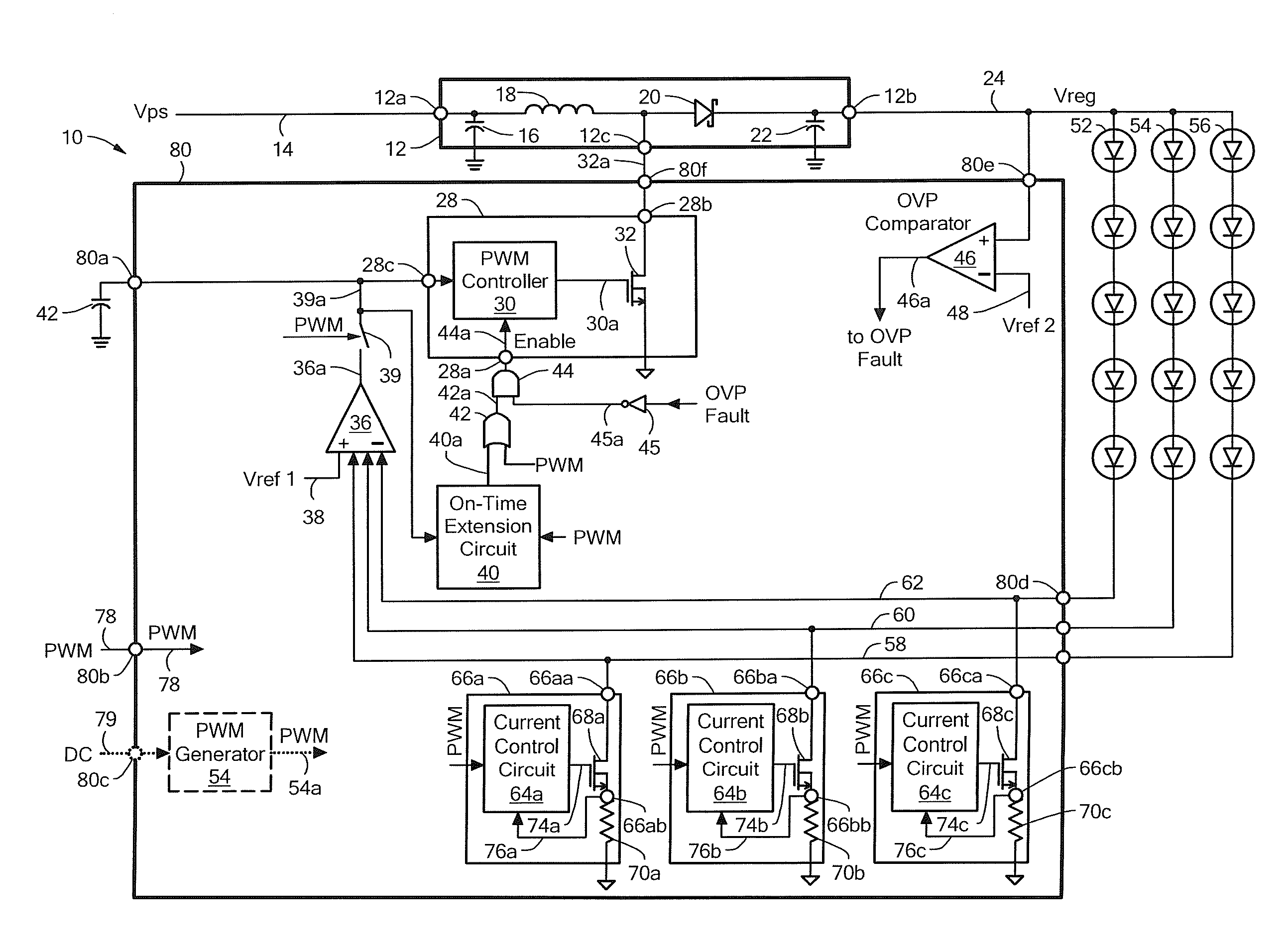
[0027]Before describing the present invention, some introductory concepts and terminology are explained. As used herein, the term “boost switching regulator” is used to describe a known type of switching regulator that provides an output voltage higher than an input voltage to the boost switching regulator. While a certain particular circuit topology of boost switching regulator is shown herein, it should be understood that boost switching regulators have a variety of circuit configurations. As used herein, the term “buck switching regulator” is used to describe a known type of switching regulator that provides an output voltage lower than an input voltage to the buck switching regulator. It should be understood that there are still other forms of switching regulators other than a boost switching regulator and other than a buck switching regulator, and this invention is not limited to any one type.

[0028]DC-DC voltage converters (or simply DC-DC converters) are described herein. The ...


PUM


Abstract

An electronic circuit, referred to as an on-time extension circuit herein, provides an ability to adjust a power delivered to a load by pulsing a predetermined current to the load. The on time of the a DC-DC converter used to provide the power iS extended to be longer than the on time of the current pulse when the on time of the current pulses becomes very short.

Description

CROSS REFERENCE TO RELATED APPLICATIONS[0001]Not Applicable.STATEMENT REGARDING FEDERALLY SPONSORED RESEARCH[0002]Not Applicable.FIELD OF THE INVENTION[0003]This invention relates generally to electronic circuits and, more particularly, to electronic circuits used to drive a load, for example, a light emitting diode (LED) load.BACKGROUND OF THE INVENTION[0004]A variety of electronic circuits are used to drive loads and, more particularly, to control electrical current through strings of series connected light-emitting diodes (LEDs), which, in some embodiments, form an LED display, or, more particularly, a backlight for a display, for example, a liquid crystal display (LCD). It is known that individual LEDs have a variation in forward voltage drop from unit to unit. Therefore, the strings of series connected LEDs can have a variation in forward voltage drop.[0005]Strings of series connected LEDs can be coupled to a common DC-DC converter, e.g., a switching regulator, e.g., a boost sw...

Claims


Application Information

Patent Timeline
Patent Type & Authority Applications(United States)
IPC IPC(8): H05B37/00G05F1/46H05B44/00
CPCH05B33/0887H05B33/0827H05B45/50H05B45/46H05B45/38H05B45/325H05B45/395H05B45/59H05B45/3725H05B31/50
Inventor SZCZESZYNSKI, GREGORY
Owner ALLEGRO MICROSYSTEMS INC
Why Eureka
Try Eureka