Display device

a display device and mirror technology, applied in the field of display devices, can solve the problems of reducing the integrated display quality of the display, user's inability to adjust the area ratio between the display region and the mirror region, etc., and achieve the effect of slow charging particle migration and easy control of the variation of electrical fields

Inactive Publication Date: 2013-01-10
CHUNGHWA PICTURE TUBES LTD
View PDF7 Cites 6 Cited by
  • Summary
  • Abstract
  • Description
  • Claims
  • Application Information

AI Technical Summary

Benefits of technology

[0007]Accordingly, the invention is directed to a display device having a mirror reflective function and meanwhile keeping the good display quality.
[0021]Based on the depiction above, since the electrophoresis unit of the invention has a plurality of charged particles therein and the charged particles have mirror reflective property, so that a user can adjust a voltage difference to change the distribution of the charged particles according to the application need and the display device is accordingly in a complete mirror reflective status, a local display plus local minor reflective status or a complete display status. In this way, the display device of the invention can have mirror reflective function and keep the original display quality. In addition, since the electrophoresis unit of the invention has a plurality of display electrodes, which can easily control the variation of the electrical field and avoid the problems of uneven distribution and slow migrating of the charged particles.

Problems solved by technology

However, the area ratio between display region and mirror region in the design is fixed, so that a user is unable to adjust the area ratio between display region and mirror region according to the requirement thereof.
In addition, since the light emitted from a backlight module needs to pass through an additional polarized lens, the integrated display quality of the display is reduced.

Method used


Image

  • Display device
  • Display device
  • Display device

Examples


Embodiment Construction

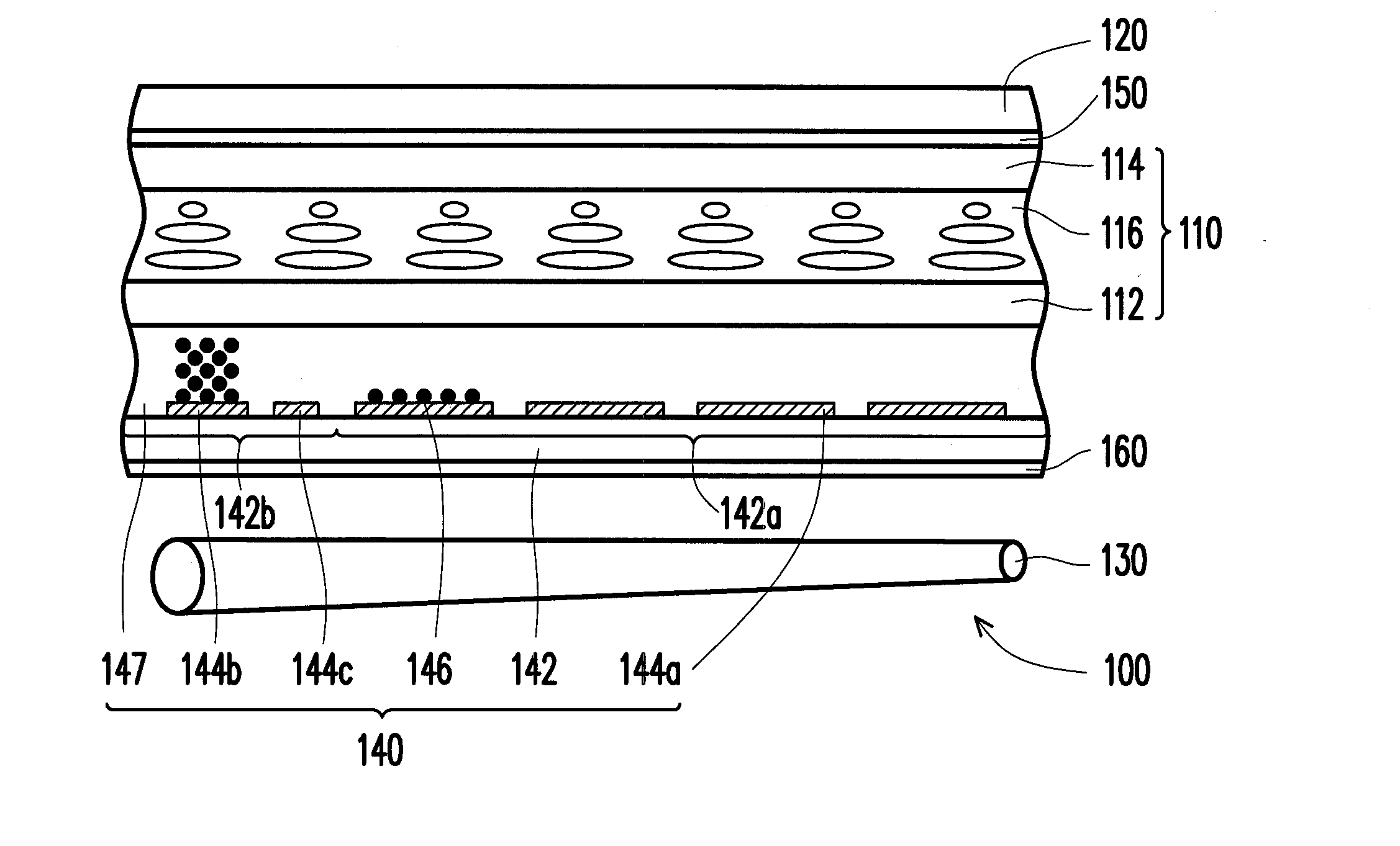
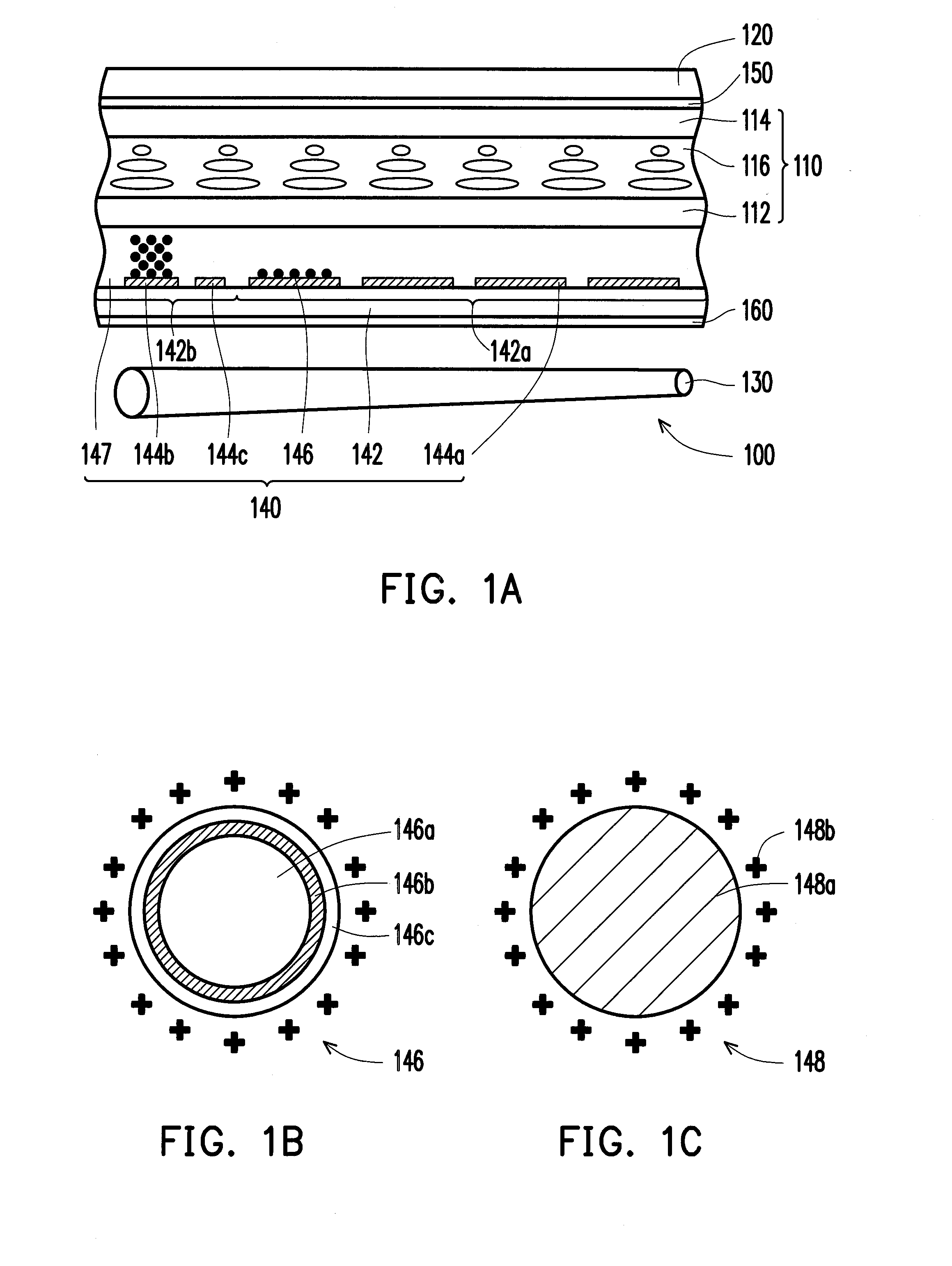
[0034]FIG. 1A is a cross-sectional diagram of a display device according to an embodiment of the invention. FIG. 1B is an enlarged schematic diagram of a charged particle in FIG. 1A according to an embodiment of the invention. FIG. 1C is an enlarged schematic diagram of a charged particle in FIG. 1A according to another embodiment of the invention. Referring to FIG. 1A at first, in the embodiment, a display device 100 includes a display unit 110, a touch unit 120, a backlight unit 130 and an electrophoresis unit 140. The touch unit 120 is disposed over the display unit 110, the backlight unit 130 is disposed under the display unit 110 and the electrophoresis unit 140 is disposed between the display unit 110 and the backlight unit 130.

[0035]In more details, the touch unit 120 is, for example, a resistive touch panel, a capacitive touch panel, an optical touch panel, an acoustic touch panel or an electromagnetic touch panel, which the invention is not limited to. The display unit 110 ...


PUM

PropertyMeasurementUnit
diameteraaaaaaaaaa
voltageaaaaaaaaaa
voltageaaaaaaaaaa

Abstract

A display device includes a display unit, a touch unit, a backlight unit and an electrophoresis unit. The touch unit is disposed over the display unit, the backlight unit is disposed under the display unit and the electrophoresis unit is disposed on the display unit, in which the electrophoresis unit includes a substrate, multiple display electrodes, at least one storage electrode, a gate electrode and multiple charged particles. The substrate has an active region and a peripheral region connecting the active region, the display electrodes are disposed at the active region of the substrate and arranged in a same interval, the storage electrode is disposed at the peripheral region of the substrate, the gate electrode is disposed at the peripheral region of the substrate and located between the display electrodes and the storage electrode, and the charged particles are disposed on the substrate have with mirror reflective property.

Description

CROSS-REFERENCE TO RELATED APPLICATION[0001]This application claims the priority benefit of Taiwan application serial no. 100123512, filed on Jul. 4, 2011. The entirety of the above-mentioned patent application is hereby incorporated by reference herein and made a part of this specification.BACKGROUND OF THE INVENTION[0002]1. Field of the Invention[0003]The invention generally relates to a display device, and more particularly, to a display device with mirror reflective function.[0004]2. Description of Related Art[0005]Along with the progressing science and technology, all digital tools such as mobile phone, digital camera, digital video camera, notebook and desktop computer are developed towards more handiness, multiple functions and nice look. In these information products, a display panel is an inevitable man-machine interface, and a user has more convenient manipulation on the products through the display function of the display panel.[0006]In terms of practicality, if a display...

Claims


Application Information

Patent Timeline
Patent Type & Authority Applications(United States)
IPC IPC(8): G06F3/041G02F1/167G02F1/1677
CPCG02F1/167G02F2201/44G02F1/1347G02F1/13338G02F1/1677
Inventor CHEN, WEN-ZHENG
Owner CHUNGHWA PICTURE TUBES LTD
Why Eureka
Try Eureka