Route generation system, route generation method, and program

a technology of route generation and route generation method, applied in surveying and navigation, navigation instruments, instruments, etc., can solve the problems of difficult to grasp the current state through ground-based observation, and the driver may not be able to pass through such a region

Inactive Publication Date: 2013-01-10
HITACHI LTD
View PDF10 Cites 31 Cited by
  • Summary
  • Abstract
  • Description
  • Claims
  • Application Information

AI Technical Summary

Problems solved by technology

However, in a region where roads are undeveloped or in a region where roads become impassable due to a disaster, the driver may not be able to pass through such a region because the driver cannot obtain information indicating how to pass through the region.
In the above-descried situation, it may be difficult to grasp the current states through ground-based observation.

Method used


Image

  • Route generation system, route generation method, and program
  • Route generation system, route generation method, and program
  • Route generation system, route generation method, and program

Examples


first embodiment

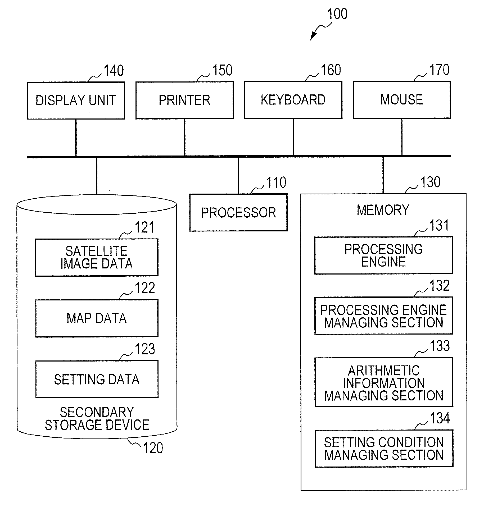
[0035]FIG. 1 is a functional block diagram schematically showing the configuration of a route generation device 100 according to a first embodiment of the present invention. The route generation device 100 includes a processor 110, a secondary storage device 120, a memory 130, a display unit 140, a printer 150, a keyboard 160, and a mouse 170. Furthermore, the route generation device 100 is provided with a network interface (not shown) and is capable of receiving sensor data from an external sensor via a network.

[0036]The processor 110 is an arithmetic device, such as a CPU (central processing unit) or an MPU (micro processing unit), and executes programs stored in the memory 130. Furthermore, the processor 110 controls functional sections of the route generation device 100. For convenience of explanation, a description will be given below of cases where actions are performed by the programs; however, these programs are actually executed by the processor 110.

[0037]The secondary stor...

second embodiment

[0092]In the first embodiment, even when no roads exist, the optimum route that passes through the start point and the end point, set in advance, can be generated by using the satellite image data 121 and the map data 122. On the other hand, when the destination is not clear or when a target area is wide, it is conceivable that the user does not know where the end point should be set.

[0093]Therefore, in a second embodiment, a description will be given of an example configuration in which spot candidates for an end point, which is the destination, are extracted from the satellite image data 121 and the map data 122, and the end point is determined in consideration of routes. Since the other configurations are the same as those of the first embodiment, a description will be given below mainly of the differences from the first embodiment.

[0094]FIG. 6 is a diagram showing a module configuration of the processing engine 131 provided in the route generation device 100 of the second embodi...

third embodiment

[0106]In the second embodiment, a description has been given of the processing of the route generation device 100 to which the function of extracting destination candidates (target areas) is added. When there are a plurality of target areas, the user may need to determine which area should be the destination or the order in which the user accesses a plurality of destinations. Therefore, in a third embodiment, a description will be given of processing of determining the priorities of a plurality of target areas. Since the other configurations are the same as those of the first and second embodiments, a description will be given below mainly of the differences from the first and second embodiments.

[0107]FIG. 7 is a diagram showing a module configuration of the processing engine 131 provided in the route generation device 100 of the third embodiment. In the third embodiment, the processing engine 131 includes a priority determining section 1319 in addition to the configurations describ...


PUM


Abstract

Provided is a route generation device capable of generating an appropriate route. A route generation system of one embodiment of the present invention includes: analysis sections that analyze aerial image data to identify the land state of an area included in an aerial image; a storage section that stores traffic cost information associating a traffic-cost coefficient indicating traffic difficulty with the land state; a route searching section that calculates traffic costs of a plurality of routes from a start point to an end point by referring to the analysis results of the analysis sections and the traffic cost information and that determines a route candidate to be used from the start point to the end point based on the calculation results.

Description

CLAIM OF PRIORITY[0001]The present application claims priority from Japanese patent application JP 2011-150876 filed on Jul. 7, 2011, the content of which is hereby incorporated by reference into this application.FIELD OF THE INVENTION[0002]The present invention relates to a route generation system, a route generation method, and a program for causing a computer to execute route generation.BACKGROUND OF THE INVENTION[0003]There are technologies in which, when the destination is set, the current location is grasped, and the optimum driving route is selected and presented, like those used in car navigation systems. Furthermore, there are technologies in which a road is estimated from the actual driving history of a vehicle etc. even in a situation in which a road map does not reflect the current states because information of the road map has not been updated, for example.[0004]In a technology described in Japanese Unexamined Patent Application Publication No. Hei11-119647, held road d...

Claims


Application Information

Patent Timeline
Patent Type & Authority Applications(United States)
IPC IPC(8): G01C21/36
CPCG01C21/3461G01C21/20
Inventor KAZAMA, YORIKOKUJIRAI, TOSHIHIROWATANABE, TAKASHI
Owner HITACHI LTD
Why Eureka
Try Eureka