Humidity control in a refrigerated transport container with an intermittently operated compressor

a technology of refrigerated transport containers and compressors, which is applied in the direction of refrigeration devices, refrigerators/freezers, sustainable buildings, etc., can solve the problems of no longer being able to identify the optimal dehumidification need indicator, and the factors of increasing the condensation or deposition rate of water vapour are not working so straightforwardly in relation to the intermittently operated compressors

Inactive Publication Date: 2013-01-17
A P MOLLER AS
View PDF9 Cites 34 Cited by
  • Summary
  • Abstract
  • Description
  • Claims
  • Application Information

AI Technical Summary

Benefits of technology

[0053]In one embodiment, the second predetermined dehumidification need threshold (RHlim2) is lower than or equal to the third predetermined dehumidification need threshold (RHlim3).
[0054]An advantage of RHlim2<RHlim3 is that only when relative humidity is far too high (RH>RHlim3) as a last option the control calls upon the least energy-efficient step of activating the heating unit while the compressor is in the second less active state.
[0055]In one embodiment, the state of heating unit, compressor and evaporator fans may only change if one or more minimum duration times for being in a given state for

Problems solved by technology

However, using an intermittently operated compressor as opposed to using a continuously running compressor in order to save energy presents a new situation for dehumidification control.
The two factors of increasing condensation or deposition rate of water vapour described above are not working so straightforwardly in relation to an intermittently operated compressor.
A further issue is how to indicate a need for dehumidification when using an intermittently operated compressor as an intermittently operated co

Method used


Image

  • Humidity control in a refrigerated transport container with an intermittently operated compressor
  • Humidity control in a refrigerated transport container with an intermittently operated compressor
  • Humidity control in a refrigerated transport container with an intermittently operated compressor

Examples


Embodiment Construction

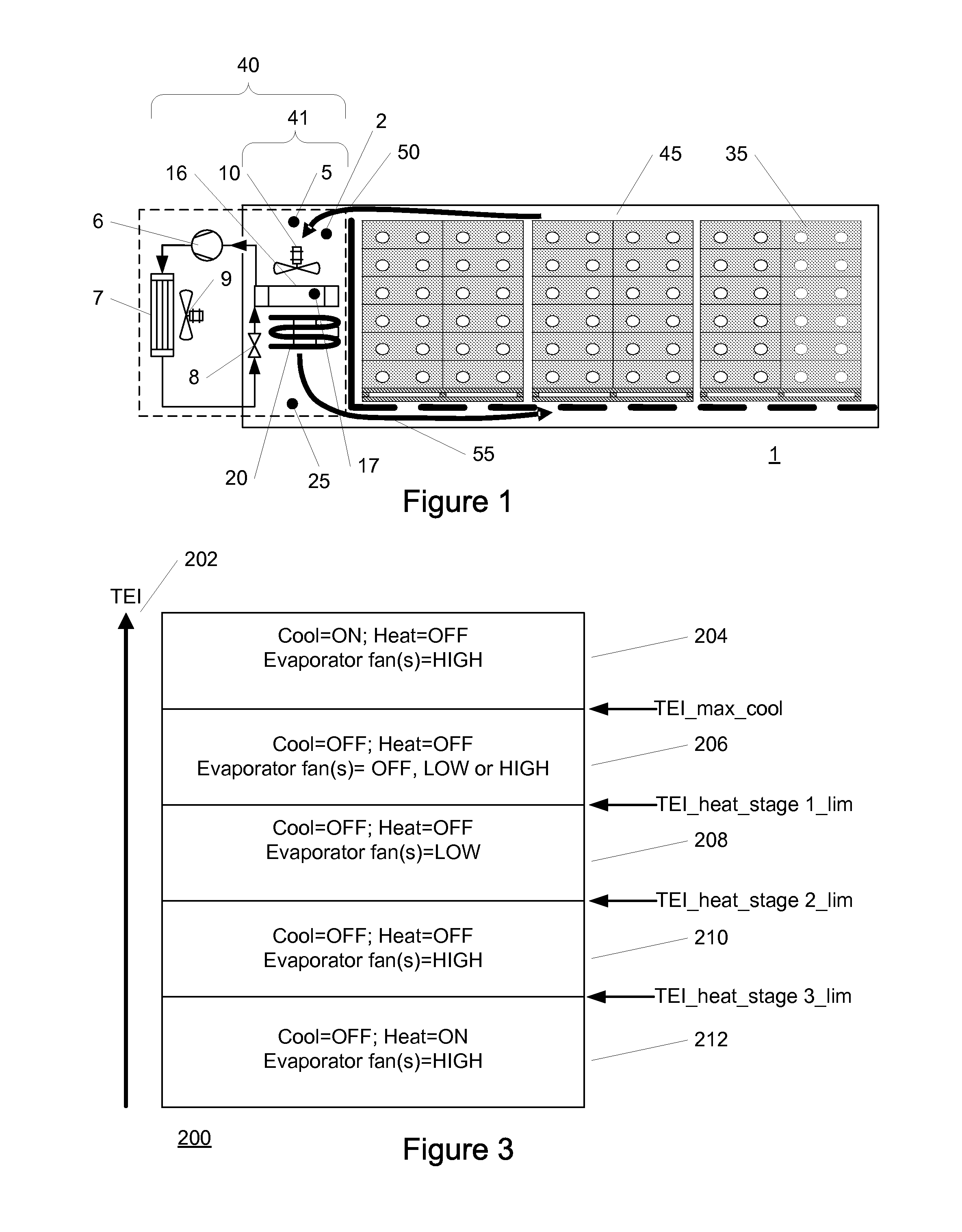
[0070]FIG. 1 schematically illustrates a simplified longitudinal cross-sectional view of a refrigerated space in the form of a refrigerated transport container. Shown in FIG. 1 is one example of a refrigerated transport container 1 comprising a frontal section having a cooling unit or system 40 and a load / cargo section or transport volume 45. The transport volume 45 of the refrigerated transport container 1 comprises a commodity load e.g. comprising a plurality of stackable transport cartons or crates 35 arranged within the transport volume 45 such as to leave appropriate clearance at a ceiling and a floor structure for air flow passages above and beneath the commodity load.

[0071]The cooling unit 40 in this example comprises a so-called vapour compression refrigeration circuit and a cooling space 41. The refrigeration circuit at least comprises a compressor 6, a condenser 7 with one or more condenser fans 9, an expansion device 8 and an evaporator 16 with one or more evaporator fans...


PUM


Abstract

There is a growing need for dehumidification control in refrigerated transport containers with an intermittently operated compressor. The disclosed system and method of dehumidification control, controlling the speed of one or more evaporator fans and a heating unit, meets that need using one or more dehumidification need indicators and one or more condensation indicators. More specifically a system for and method is disclosed, comprising: controlling the operation of the one or more evaporator fans (10) for dehumidification purposes according to: if a need for dehumidification is determined using at least one dehumidification need indicator and if at least one condensation indicator indicates that the evaporator (16) is sufficiently cold respectively too warm for condensation or deposition of water vapor on its external surface, then setting or maintaining the speed of the one or more evaporator fans (10) to a reduced speed (LOW) in order to increase a condensation or deposition rate respectively to an increased speed (HIGH) in order to increase heat load to the evaporator (16), respectively. In other embodiments the system and method controls the heating unit as well.

Description

[0001]The present invention relates to a method of and a system for dehumidification control in a refrigerated transport container thereby controlling relative humidity within a refrigerated storage space with an intermittently operated compressor.BACKGROUND OF THE INVENTION[0002]Temperature in a refrigerated storage space is controlled within a temperature range adjacent to a setpoint or target temperature. The refrigerated storage space may for example comprise a transport volume of a refrigerated transport container. The setpoint temperature is chosen to keep perishable produce such as meat, vegetables and fruit or other, at correct temperatures to avoid quality degradation.[0003]In many shipments of perishable goods, not only should the temperature be controlled, but the humidity should be decreased as well to protect the carried commodity from mould growth and / or condensation. Humidity in a refrigerated storage space is then controlled within a humidity range adjacent to a setp...

Claims


Application Information

Patent Timeline
IPC IPC(8): F25D17/06F25B49/00
CPCF25D2317/04111F25D11/003F25D17/042Y02B30/743F25D2400/02Y02B40/32F25B2600/112Y02B30/70Y02B40/00
Inventor LUKASSE, LEIJN JOHANNES SJERPDE KRAMER-CUPPEN, JANNEKE EMMY
Owner A P MOLLER AS
Why Eureka
Try Eureka