Adjusting rigid foil spar system

a rigid foil and spar system technology, applied in the field of rigid foil sails for boats, can solve the problems of reducing the efficiency of a conventional sail, so as to achieve the effect of easy adjustment of camber

Inactive Publication Date: 2013-01-17
HOYT JOHN GARRISON
View PDF9 Cites 26 Cited by
  • Summary
  • Abstract
  • Description
  • Claims
  • Application Information

AI Technical Summary

Benefits of technology

[0009]In this regard, the present invention provides for a three dimensional rigid foil sail design. As such, the general purpose of the present invention, which will be described subsequently in greater detail, is to provide at least a three part rigid foil sail having a full length vertical leading edge whose trim angle / angle of attack is controlled by the main sheet and at least two trailing edge flaps attached rearwardly of the leading edge, each of which can be independently trimmed from a convenient deck level control tray to achieve easily adjustable camber.
[0010]The design of the rigid foil sail of the present invention allows depowering of the sail without altering mainsheet trim by decreasing the camber of the upper trailing flap thus also decreasing the heeling force created by the power of the upper trailing flap. Such an arrangement allows the boat to be driven without the loss of upwind pointing performance and without the loss of power caused by luffing of the sail. Similarly, the boat can be better balanced by trimming the lower trailing flap for optimum performance and simultaneously trimming the upper trailing flap neutral or even to leeward to create an opposing force that will counter the heeling moment of the sail allowing the boat to be driven to windward more efficiently with a minimum heel angle.
[0011]Therefore, it is an object of the present invention to provide a rigid foil sail that has adjustable camber that is also capable of being detuned to allow its use in heavier wind conditions. It is a further object of the present invention to provide a self-supporting rigid foil sail that includes adjustable camber to increase or decrease the power generated by the foil shape. It is still a further object of the present invention to provide a rigid foil sail that includes at least two adjustable trailing sections to allow independent adjustment of the sail camber in a manner that better balances the boat without compromising upwind pointing performance.

Problems solved by technology

The sail, however, is considerably the less efficient foil of the two partly because the sail utilizes a single surface air foil as opposed to the more efficient double surface air foil of the wing.
Another factor that reduces the efficiency of a conventional sail is that its external bracing, mast and rigging disturb the flow of air around its surface, resulting in an energy loss to turbulence and drag.
Despite its much greater efficiency, a standard wing does not make a good sail when mounted in a vertical position so that the lift that it generates can be used as thrust to drive a boat or vehicle.
A close review of the prior art in this area reveals that the design and construction of such variable camber wings have been complex and in fact impractical when considered on a commercial production basis.
It has, however, a fault in that it is difficult to handle and troublesome to lower.
Further, the airfoil shape of the sail can only be achieved effectively with the various segments fully extended vertically.
Further shortcomings originate from the excessively complicated construction of the sail, which is also the cause for high cost and low reliability.
Finally, such sail arrangements are generally heavy.
Should the vessel overturn the prior art rigid sails risk filling with water, compromising both the floatation of the sail and the boat.

Method used


Image

  • Adjusting rigid foil spar system
  • Adjusting rigid foil spar system
  • Adjusting rigid foil spar system

Examples


Embodiment Construction

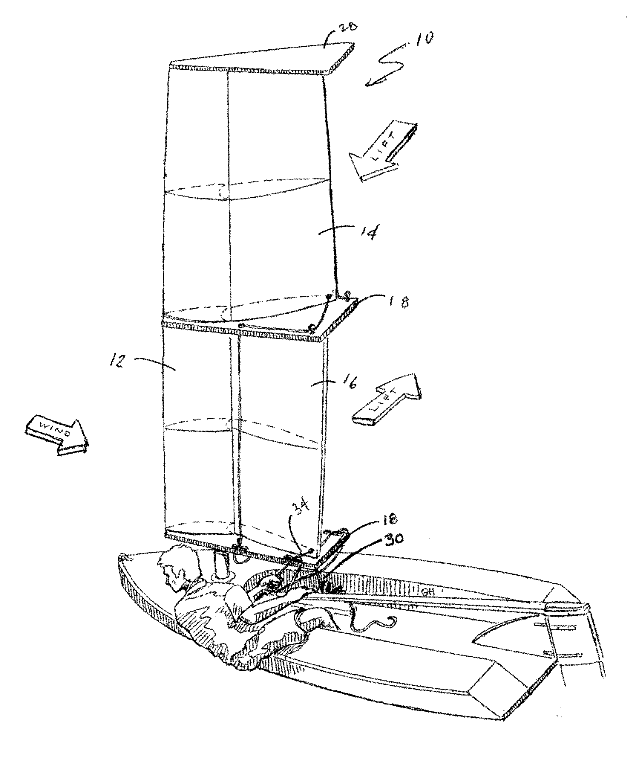
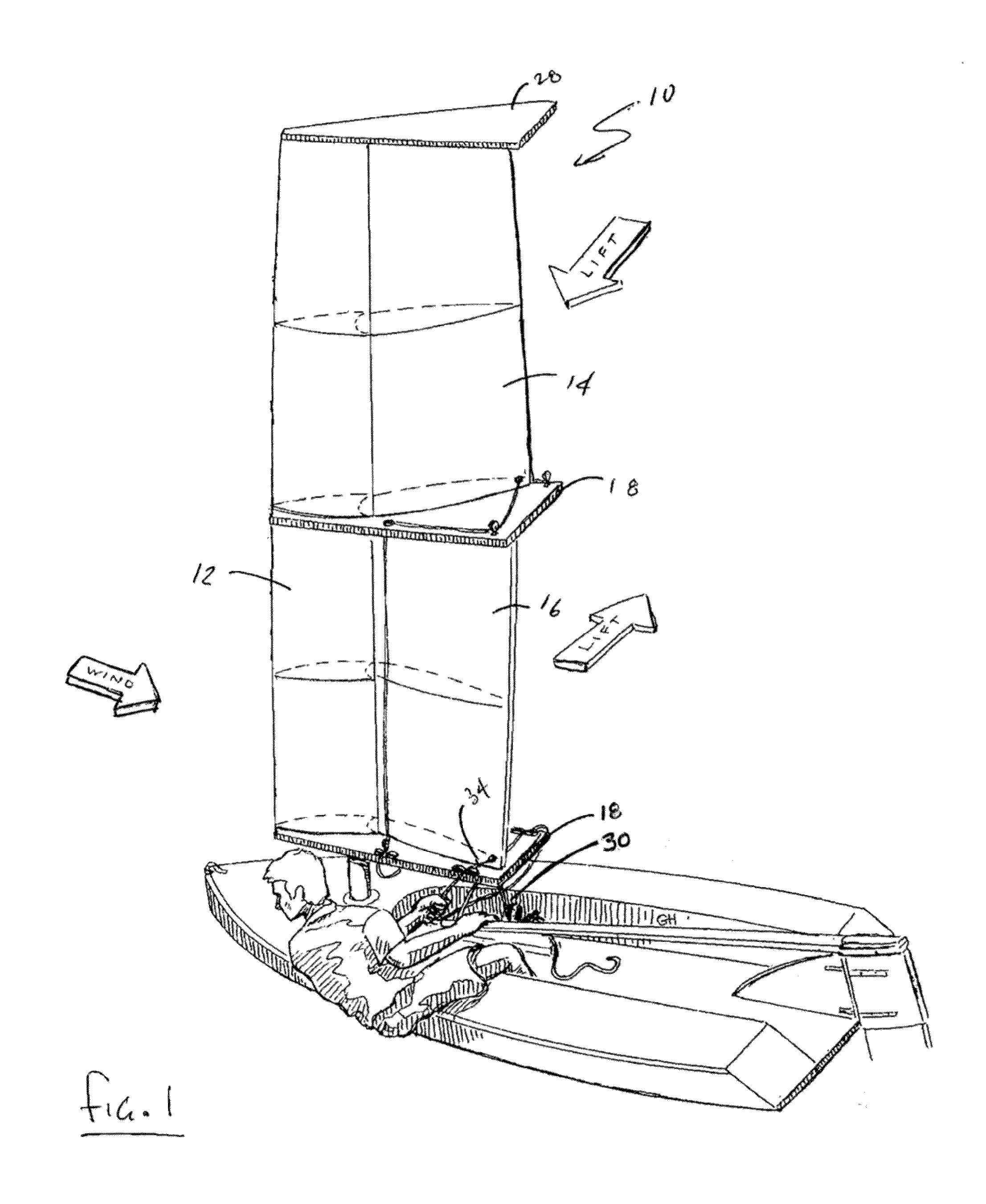
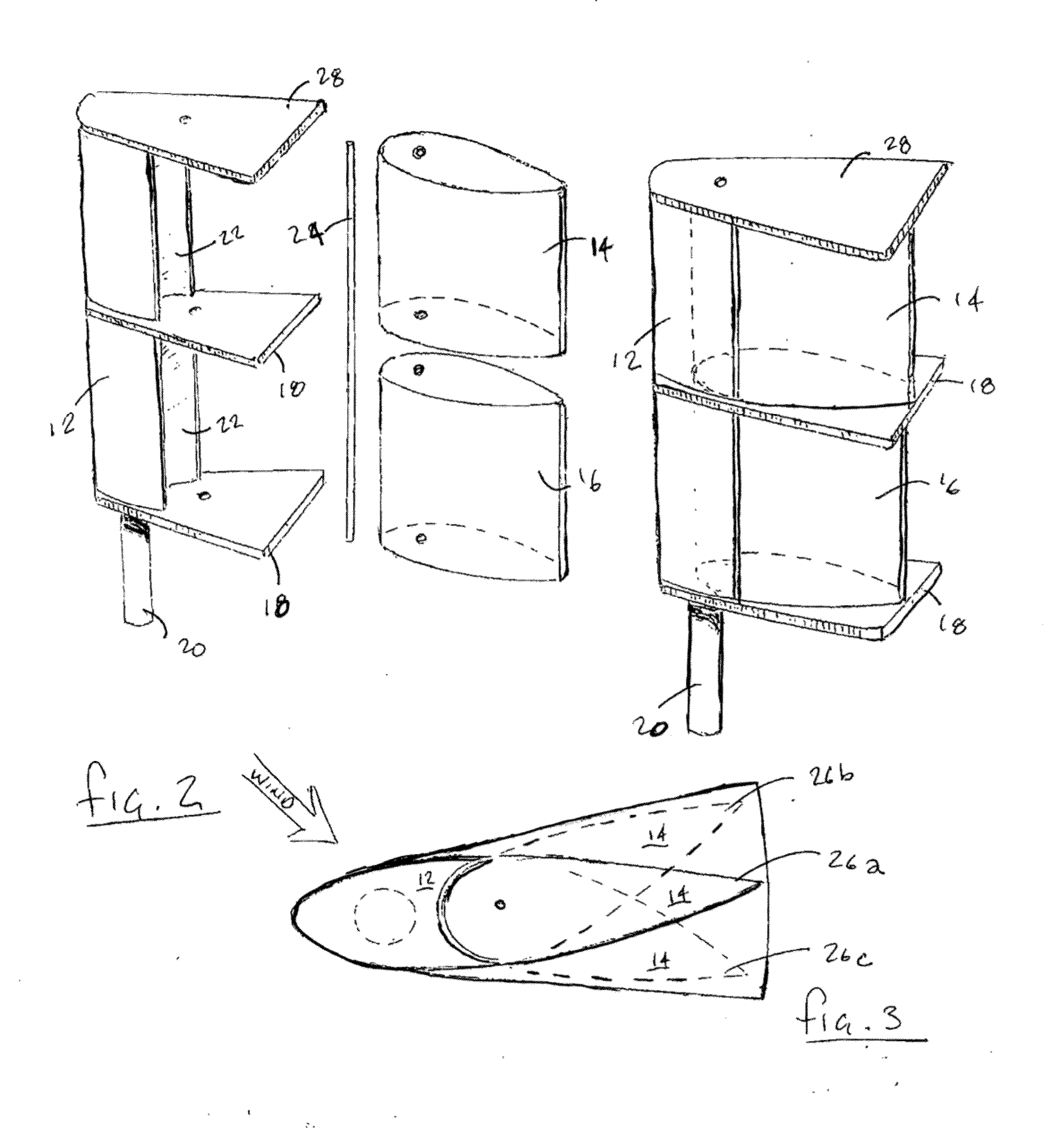
[0022]Now referring to the drawings, the three dimensional rigid foil sail design is generally shown and illustrated at 10. As can be seen at FIG. 1, the present invention generally provides at least a three part rigid foil sail 10 having a full length vertical leading edge 12 whose trim angle / angle of attack is controlled by the main sheet and at least two trailing edge flaps 14, 16 attached rearwardly of the leading edge 12, each of which can be independently trimmed from a convenient deck level control tray to achieve easily adjustable camber. Further, the rigid foil sail 10 can be seen to include control trays 18 at the bottom of each of the trailing edge flaps 14 and 16 that allow independent adjustment of the camber for each section of the rigid foil sail 10 independently of one another.

[0023]It can be seen from FIG. 1 that the rigid foil sad 10 provides a squared geometry as compared to the prior art sails. Such squared geometry can be achieved due to the rigid nature of the ...


PUM


Abstract

A rigid foil sail having a full length vertical leading edge whose trim angle / angle of attack is controlled by the main sheet and trailing edge flaps attached rearwardly of the leading edge, each of which can be independently trimmed from a convenient deck level control tray to achieve easily adjustable camber. The design of the rigid foil sail allows depowering of the sail without altering mainsheet trim by decreasing the camber of the upper trailing flap thus also decreasing the heeling force created by the power of the upper trailing flap. Further, a void within the foil is filled with a lighter than air gas to assist in countering heeling moment to allow the boat to be driven without the loss of upwind pointing performance and without the loss of power and also allowing the boat to be driven to windward more efficiently with a minimum heel angle.

Description

CROSS-REFERENCE TO RELATED APPLICATIONS[0001]This application is a Continuation in Part Application of U.S. patent application Ser. No. 13 / 180,633, filed Jul. 11, 2011, which is related to and claims priority from earlier filed U.S. Provisional Patent Application No. 61 / 483,996, filed May 9, 2011, the contents of which are incorporated herein by reference.BACKGROUND OF THE INVENTION[0002]The present invention relates generally to rigid foil sails for boats. More specifically, the present invention relates to a rigid foil sail system for boats that has independently controllable sections that allow optimum control over the lift force generated by the soil in varying wind conditions and directions.[0003]Although the appearance of the conventional sail is quite different from that of an aircraft wing, its function in generating a positive force is based on the same aerodynamic principles as those applied to a wing. The sail, however, is considerably the less efficient foil of the two p...

Claims


Application Information

Patent Timeline
Patent Type & Authority Applications(United States)
IPC IPC(8): B63H9/06B63H9/04B63H9/10
CPCB63H9/0607B63B2035/009B63H9/0635B63H9/061
Inventor HOYT, JOHN GARRISON
Owner HOYT JOHN GARRISON
Why Eureka
Try Eureka