Method for working out the angular position of a rotating element and device for carrying out such a method

Active Publication Date: 2013-01-17
CSEM CENT SUISSE DELECTRONIQUE & DE MICROTECHNIQUE SA RECH & DEV
View PDF5 Cites 5 Cited by
  • Summary
  • Abstract
  • Description
  • Claims
  • Application Information

AI Technical Summary

Benefits of technology

The invention is a device that can accurately measure the position of a rotating device, even if there are mechanical imperfections in the bearings. It can also measure the wear of the device over time by measuring how much the device is deviating from a fitted circle. The device is very versatile and can be used in different technical applications, such as rotary encoders for end-of-shaft arrangements. It is also small in size and can provide high resolution and accuracy. The device contains two light sources that provide a precise and absolute angular position, even if the rotation axis drifts during operation. The device is cost-effective and can operate in high temperature environments. The mask is fixed to the sensor, enhancing its thermal and mechanical stability, and no plastic parts are needed. This technology can improve the accuracy and reliability of rotating devices.

Problems solved by technology

However, a main drawback of such a device is that the positioning of the sensor with respect to the axis needs to be very precise.
The costs resulting of such a positioning operation, is very high.
The cost of a ring-shaped sensor or multiple sensor arrangement is also very expensive.
In addition, such a device cannot be made very small.

Method used


Image

  • Method for working out the angular position of a rotating element and device for carrying out such a method
  • Method for working out the angular position of a rotating element and device for carrying out such a method
  • Method for working out the angular position of a rotating element and device for carrying out such a method

Examples


first embodiment

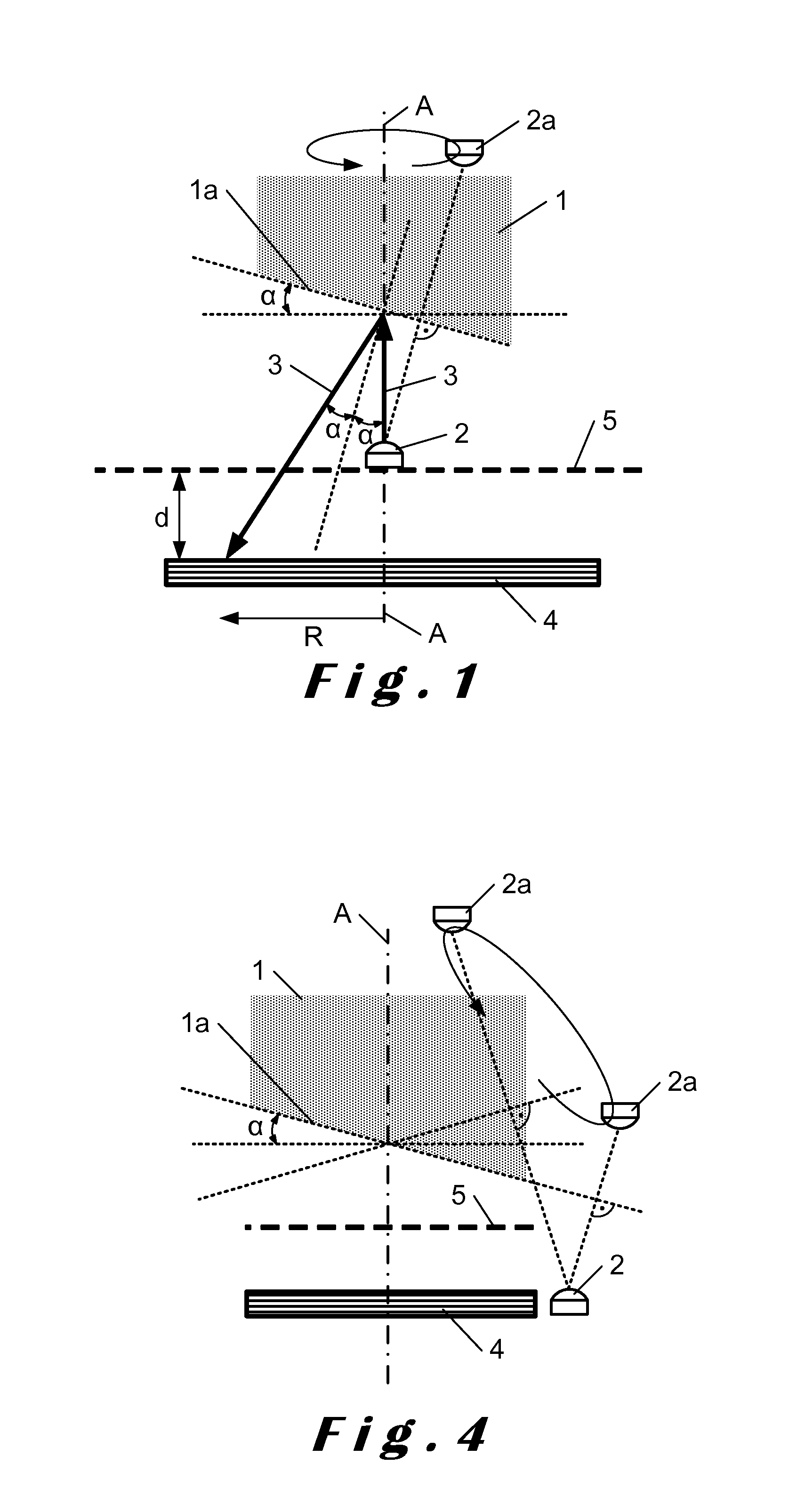
[0061]FIG. 1 illustrates a device in accordance with the invention, for providing the angular position of a rotating element 1 such as a shaft, which is able to rotate in a fixed frame. The device comprises a point-light source 2, which may be a Light Emitting Diode (LED), emitting a light beam 3.

[0062]The device comprises also optical transmission means localized on the path of the light beam 3 and influencing the light beam 3 in dependence on the angular position of the rotating element 1.

[0063]The device comprises also a sensor 4 extending in a plane which is orthogonal to the rotation axis A of the rotating element 1. The sensor 4 comprises a pixel array which is hit by the influenced light beam 3.

[0064]The device comprises also processing and computing means for providing the angular position of the rotating element 1 by using the output signal of the sensor 4.

[0065]The optical transmission means comprise a mask 5 which presents a two dimensional repetitive pattern of transpare...

second embodiment

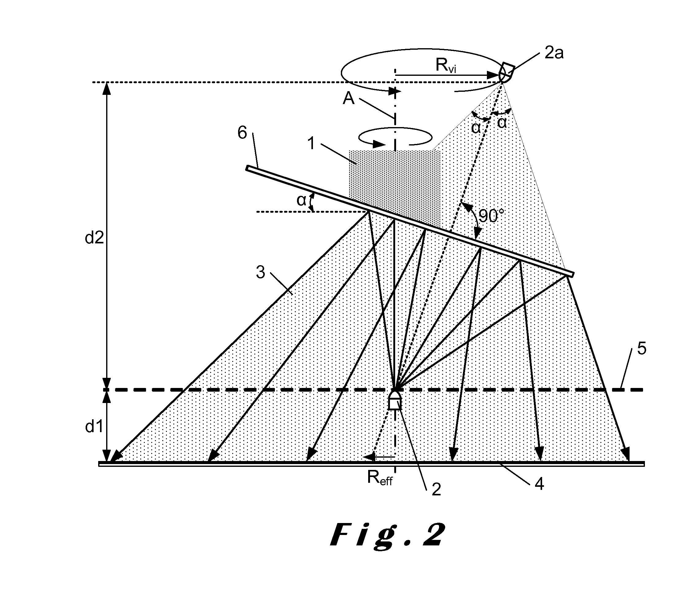
[0069]FIG. 2 illustrates a device in accordance with the invention, in which the light source 2 is arranged in a fixed position on the mask 5, aligned with the rotation axis A of the rotating element 1 and facing a tilted mirror 6 fixed on the end of the rotating element 1 for reflecting the light beam 3. The mirror 6 is advantageously fixed on the slanted end 1a of the rotating element 1.

[0070]In this embodiment, the mask 5 extends at a distance d1 from the sensor 4 and the virtual light source 2a turns in a plane which is located at a distance d2 from the mask 5.

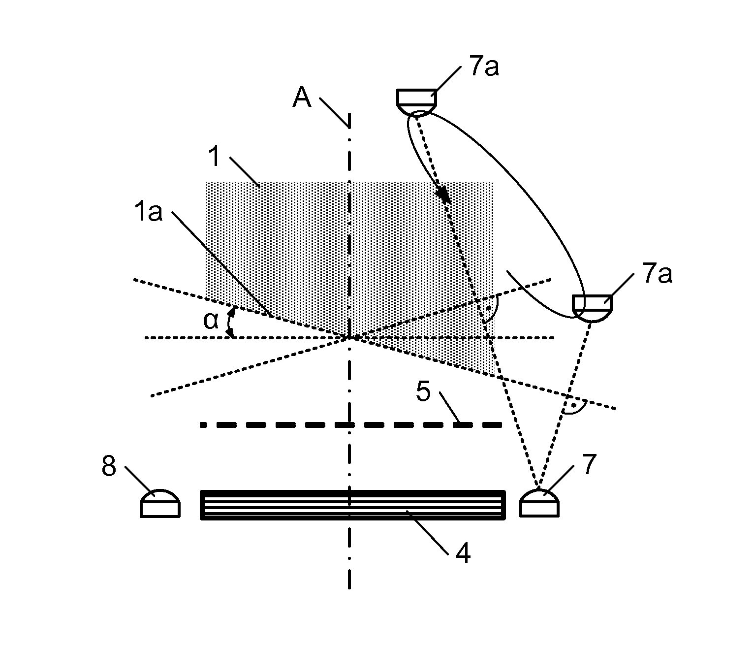
[0071]In the embodiment of FIG. 3, the device comprises two light sources 7 and 8, each light source emitting a light of different color and being arranged in a fixed an off-centered position on the mask 5. The rotating element 1 faces the mask 5 with the surface of its slanted and polished end la, for reflecting the two emitted beams of light. The fixed light sources 7 and 8 can also be represented by mobile virtual light...


PUM


Abstract

Method for working out the angular position of a rotating element, using at least one light source emitting a light beam in the direction of a fixed sensor and computing elements for processing an output signal of the sensor, includes:arranging the light source with respect to the rotating element and the sensor so as to induce an interaction between the light beam and the sensor which depends on the angular position of the rotating shaft,arranging on the path of the light beam, in a fixed position with respect to the sensor, a perforated mask which presents a repetitive pattern of perforations,detecting shadows generated by the mask on the sensor,processing the output signal of the sensor for determining the position of the shadows on the sensor, andcomputing the angular position of the rotating element using the position of the shadows.

Description

TECHNICAL FIELD[0001]The present invention relates to the technical field of the determination with high precision of the angular positions of a rotational part or element, for instance a shaft, with respect to a fixed frame or structure. Devices such as optical encoders, such as end-of-shaft encoders, which allow such a determination, are already used for instance in the field of electric actuators or motors.[0002]The present invention concerns more particularly a method for determining a reliable angular position of a rotating shaft with a very high accuracy.[0003]The present invention concerns also a device for carrying out the above mentioned method.BACKGROUND OF THE INVENTION[0004]In an application concerning a device for determining the angular position of a rotating shaft, which is disclosed in document DE 39 39 905, an angular position with high resolution and / or an absolute angular position with respect to a fixed part, can be obtained. The device comprises a fixed light so...

Claims


Application Information

Patent Timeline
IPC IPC(8): G01D5/34
CPCG01D5/285G01D5/38
Inventor MASA, PETER
Owner CSEM CENT SUISSE DELECTRONIQUE & DE MICROTECHNIQUE SA RECH & DEV
Why Eureka
Try Eureka