Antenna structure for wearable electronic device and wearable wireless electronic device

a technology of electronic devices and antennas, applied in the direction of antennas, antenna details, elongated active elements, etc., can solve the problems of poor integration of the above-mentioned structure, inconvenient use of current antenna structures, and poor wireless communication function, and achieve good wireless communication function

Inactive Publication Date: 2013-01-17
WISTRON NEWEB
View PDF13 Cites 57 Cited by
  • Summary
  • Abstract
  • Description
  • Claims
  • Application Information

AI Technical Summary

Benefits of technology

[0008]The wearable wireless electronic device of the invention includes a device casing, an antenna ground structure, a carrier, an antenna radiation structure, and a processing module. The antenna ground structure is joined with the device casing. The carrier is connected to the device casing. The antenna radiation structure is joined with the carrier. The processing module is disposed in the device casing and electrically connected to the antenna ground structure and the antenna radiation structure so as to perform wireless communication through the antenna ground structure and the antenna radiation structure. Thereby, the wearable wireless electronic device uses its original structure to dispose the antenna, so the wearable wireless electronic device can have good wireless communication function with the structure unchanged or less modification.

Problems solved by technology

In other words, the current antenna structure is not suitable for small-volume communication electronic devices.
Furthermore, the isolated space for operation is usually stationary, so the current antenna structure is disposed statically and not easily integrated with other components structurally.
Especially when the volume of the electronic device such as an electronic device worn on a wrist is small, the integration problem of the aforementioned structure becomes worse.
In general, for keeping a good antenna performance, the required space for the disposition of the antenna makes the volume of the whole device large; on the contrary, for keeping the device with small and exquisite appearance, the antenna performance is lost somewhat.
Therefore, the design for the current small wireless communication electronic device gets into the dilemma of the antenna performance and the device appearance and cannot satisfy both.

Method used


Image

  • Antenna structure for wearable electronic device and wearable wireless electronic device
  • Antenna structure for wearable electronic device and wearable wireless electronic device
  • Antenna structure for wearable electronic device and wearable wireless electronic device

Examples


Embodiment Construction

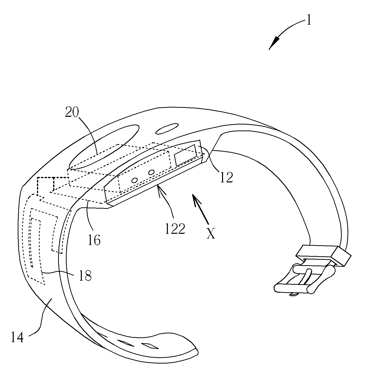
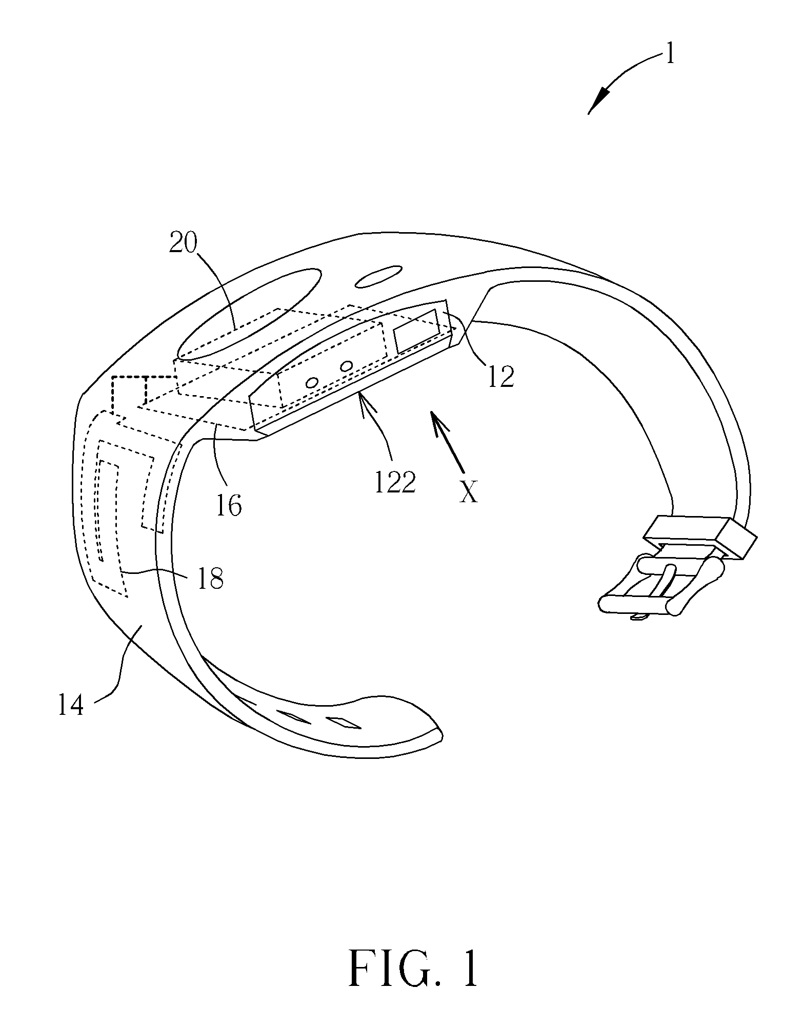
[0017]Please refer to FIG. 1. FIG. 1 is a schematic diagram illustrating wearable wireless electronic device 1 of a preferred embodiment according to the present invention. In the embodiment, the wearable wireless electronic device 1 is a wrist watch. The wearable wireless electronic device 1 includes a device casing 12, a belt carrier 14, an antenna ground structure 16, an antenna radiation structure 18, and a processing module 20. The antenna ground structure 16, the antenna radiation structure 18, and the processing module 20 are shown by dashed lines in FIG. 1. The belt carrier 14 is connected to the device casing 12. The antenna ground structure 16 is joined with the device casing 12. The antenna radiation structure 18 is joined with the belt carrier 14. The processing module 20 is disposed in the device casing 12 and electrically connected to the antenna ground structure 16 and the antenna radiation structure 18 (shown by bold dashed lines in FIG. 1) so as to perform wireless ...


PUM


Abstract

An antenna structure for wearable electronic device has a device casing, an antenna ground structure joined with the device casing, a carrier connected to the device casing, and an antenna radiation structure joined with the carrier. Thereby, the antenna structure can be integrated into the original structure of a wearable device so that the volume of the wearable device can be reduced, which solves the difficulty in reducing the volume of a wireless communication device with a requirement of an antenna disposition in the prior art. In addition, a wearable wireless electronic device has the antenna structure so as to have the advantage of smaller volume relative to a wearable wireless electronic device in the prior art.

Description

BACKGROUND OF THE INVENTION[0001]1. Field of the Invention[0002]The invention relates to an antenna structure and an electronic device, and especially relates to an antenna structure joined in a wearable electronic device and to a wearable wireless electronic device having the antenna structure.[0003]2. Description of the Prior Art[0004]As wireless communication technology develops, most current portable electronic devices have wireless communication function. The wireless communication needs a physical antenna to be the medium for transmitting or receiving signals. Moreover, based on antenna operation principle, the antenna needs a certain isolated space for operation. So the volume of the whole electronic device can be hardly reduced, even though other components thereof can be reduced in volume. In other words, the current antenna structure is not suitable for small-volume communication electronic devices. Furthermore, the isolated space for operation is usually stationary, so th...

Claims


Application Information

Patent Timeline
Patent Type & Authority Applications(United States)
IPC IPC(8): H01Q1/24H01Q1/12
CPCH01Q1/273H01Q5/371H01Q9/42
Inventor LIN, CHIA-HONGCHOU, JUI-HSIANGCHEN, I-SHAN
Owner WISTRON NEWEB
Why Eureka
Try Eureka