
Antenna structure of carry-on electronic device and carry-on wireless electronic device

An antenna structure and wireless electronic technology, applied in the directions of antenna, radiating element structure, antenna support/installation device, etc., can solve the problems of difficult to reduce the size of portable electronic devices, serious structural integration, and uncomfortable volume of communication electronic devices.

Inactive Publication Date: 2013-01-23
WISTRON NEWEB
View PDF1 Cites 2 Cited by
  • Summary
  • Abstract
  • Description
  • Claims
  • Application Information

AI Technical Summary

Problems solved by technology

Since wireless communication usually requires a physical antenna as a medium for signal transmission and reception, and based on the operating principle of the antenna, the current antenna still needs a considerable independent operating space, so even if the size of other electronic components can be reduced, the size of the entire portable electronic device is still difficult to reduce
In other words, most of the current antenna structure configurations are not suitable for small communication electronic devices
In addition, since the independent operating space of the antenna is mostly independent and fixed, the current antenna structure configuration is mostly static and is not easy to be structurally integrated with other components of the electronic device, especially when the electronic device is small in size, such as an electronic device worn on the wrist. The aforementioned structural integration problems will become more serious
Generally speaking, in order to maintain good antenna performance, the space required for antenna configuration will result in a large device size; on the contrary, in order to present a compact device appearance, the antenna performance must be sacrificed
Therefore, the current design of small wireless communication electronic devices often needs to choose between antenna performance and device appearance, and it is difficult to balance

Method used


Image

  • Antenna structure of carry-on electronic device and carry-on wireless electronic device
  • Antenna structure of carry-on electronic device and carry-on wireless electronic device
  • Antenna structure of carry-on electronic device and carry-on wireless electronic device

Examples


Embodiment Construction

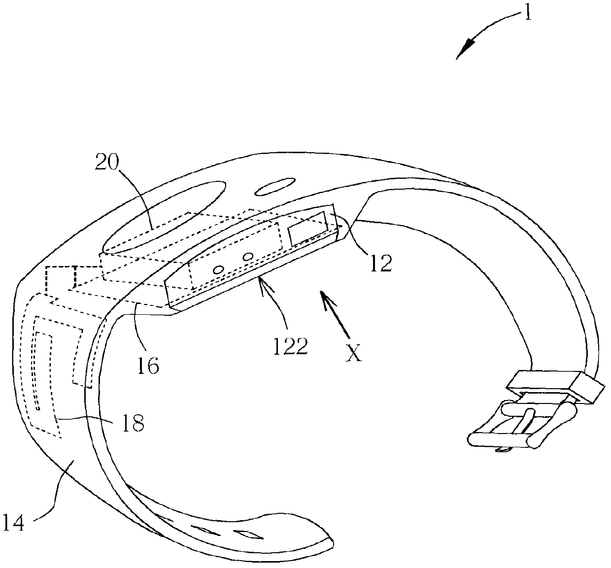
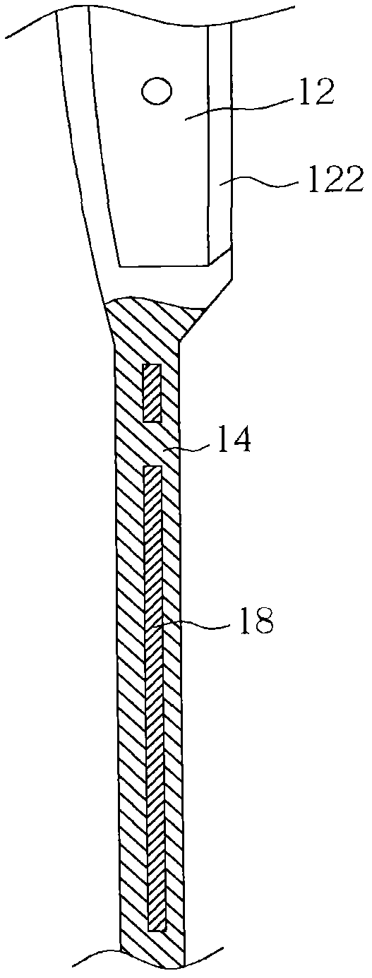
[0029] see figure 1 , which is a schematic diagram of a portable wireless electronic device 1 according to a preferred embodiment of the present invention. In this embodiment, the portable wireless electronic device 1 is a wrist watch. The portable wireless electronic device 1 includes a device housing 12, a strip carrier 14, an antenna grounding structure 16, an antenna radiation structure 18 and a processing module 20, wherein the antenna grounding structure 16, the antenna radiation structure 18 and the processing module 20 are in figure 1 Indicated by a dotted line. The tape carrier 14 is connected to the device housing 12, and the antenna ground structure 16 (shown in dashed lines on figure 1 Middle) combined with the device housing 12, the antenna radiation structure 18 (shown in dotted line in figure 1 Middle) is combined with the tape carrier 14, and the processing module 20 is arranged in the device housing 12 and is electrically connected with the antenna groundin...


PUM


Abstract

The invention discloses an antenna structure of a carry-on electronic device and a carry-on wireless electronic device. The antenna structure of the carry-on electronic device comprises a device shell, an antenna grounding structure, a carrier and an antenna radiation structure, wherein the antenna grounding structure is combined with the device shell; the carrier is connected to the device shell; and the antenna radiation structure is combined with the carrier. The antenna structure disclosed by the invention can be integrated into the original structure of the carry-on electronic device, so that the volume of the whole carry-on electronic device is reduced; and a problem that the volume of the device is hard to reduce due to the need of the antenna in a wireless communication device is solved. The carry-on wireless electronic device disclosed by the invention comprises the antenna structure; therefore, compared with the well-known carry-on wireless electronic device, the carry-on wireless electronic device disclosed by the invention has the advantage of smaller volume.

Description

technical field [0001] The invention relates to an antenna structure and a wireless electronic device, in particular to an antenna structure combined with a portable electronic device and a portable wireless electronic device with the antenna structure. Background technique [0002] With the development of wireless communication technology, most of the portable electronic devices have the function of wireless communication. Since wireless communication usually requires a physical antenna as a medium for signal transmission and reception, and based on the operating principle of the antenna, the current antenna still needs a considerable independent operating space, so even if the size of other electronic components can be reduced, the size of the entire portable electronic device is still difficult to reduce . In other words, most of the current antenna structure configurations are not suitable for small communication electronic devices. In addition, since the independent o...

Claims


Application Information

Patent Timeline
IPC IPC(8): H01Q1/36H01Q1/38H01Q1/22H01Q5/01H01Q5/10
Inventor 林佳宏周瑞祥陈毅山
Owner WISTRON NEWEB
Learn More