Flat illuminating display device and light-emitting means therefor

a technology of illuminating display device and light-emitting means, which is applied in the direction of mobile visual advertising, lighting and heating apparatus, instruments, etc., can solve the problems of large component thickness, inability to insert illuminating display devices into thin walls, and still appear to be quite thick, etc., to achieve simple light-emitting, thin and flexible, and flat illumination

Inactive Publication Date: 2013-01-17
AIRBUS OPERATIONS GMBH
View PDF1 Cites 7 Cited by
  • Summary
  • Abstract
  • Description
  • Claims
  • Application Information

AI Technical Summary

Benefits of technology

[0007]An embodiment of the present invention includes a particularly flat illuminating display device, which is particularly thin and flexible and which allows a homogeneous illuminating display of an image on a display area with technically simple light-emitting means.
[0009]The advantage of the solution according to an aspect of the invention is particularly the fact that the display area for the image comprises a flexible film, which is embodied in a particularly thin quality. Experiments have shown that warning signs of at least roughly post-card size can be manufactured by means of translucent films having a layer thickness of approximately 0.5 mm Due to the flexibility of the film, display areas can be obtained which are adapted to curved contours of surfaces. The light coupling unit according to an embodiment of the invention allows a space-saving lateral feeding in of light into the thin film. By means of the light coupling optics according to the invention, light can be fed into the thin film although the light emission area of the light source is greater than the film thickness. Thus the light of the light source is bundled onto the film thickness. In addition, by means of the light coupling unit, light is fed into the film such that it hits the film surface at an optically favourable angle to provide a light duct. The light duct and the coupling out of light are applied to the film in a simple manner by means of coating technology. This way, an efficient production of display areas of different sizes with any conceivable kind of images can be obtained, which can be embodied as, for example, pictures, pictograms, symbols, or writing.
[0011]The image arranged within the range of the display area is, preferably, directly applied to the film using an at least partly translucent colour. This may also be obtained by printing. As an alternative, it is also possible to use a second cover film comprising the at least partly translucent image and to apply it to the light-guiding film, for example, by laying it on top. By means of this measure images to be displayed can be exchanged in a simple manner.
[0012]According to a measure of the present invention, it is proposed to cover the image by a semi-translucent colour layer applied to the display area. In doing so, said semi-translucent colour layer serves the achievement of what is referred to as a disappearing effect. The disappearing effect works such that the image to be displayed is not, or only barely, visible from the outside when the light coupling unit is not switched on. The observer sees a continuously homogeneous surface, which in many cases is also shining As soon as the light coupling unit is switched on, the image lights up from the homogeneous surface. The film, which is coated differently, according to the invention, thus allows to provide a display area equipped with the disappearing effect during lateral feeding in of light.
[0015]According to another measure of the present invention, it is proposed to embody the light-emitting means as a laterally connectable light coupling unit by means of clamping bars to the translucent film having a translucent carrier unit. Said carrier unit may consist of an injection-moulded synthetic material. The clamping bars, which alternating have a clamping effect onto the upper and lower side of the film, allow a simple and releasable connection with the film and, therefore, a particularly easy assembly or disassembly.

Problems solved by technology

This illuminating display device has the disadvantage that quite a considerable component thickness results from the curved reactor segments that are arranged behind the protective cover, which requires a corresponding installation space.
Therefore, said illuminating display device cannot be inserted into thin walls without that the rear part of the reflector insert protrudes from the wall.
Because of the synthetic base body that fulfils a carrier function, said technical solution, however, still appears to be quite thick for particularly flat applications and the display surface obtainable by it possesses a level embodiment and, in addition, is inflexible.
The technical solution disclosed in DE 197 03 195 A1 has the same disadvantages, because a plurality of inflexible display plates are stacked upon one another like a sandwich.

Method used


Image

  • Flat illuminating display device and light-emitting means therefor
  • Flat illuminating display device and light-emitting means therefor
  • Flat illuminating display device and light-emitting means therefor

Examples


Embodiment Construction

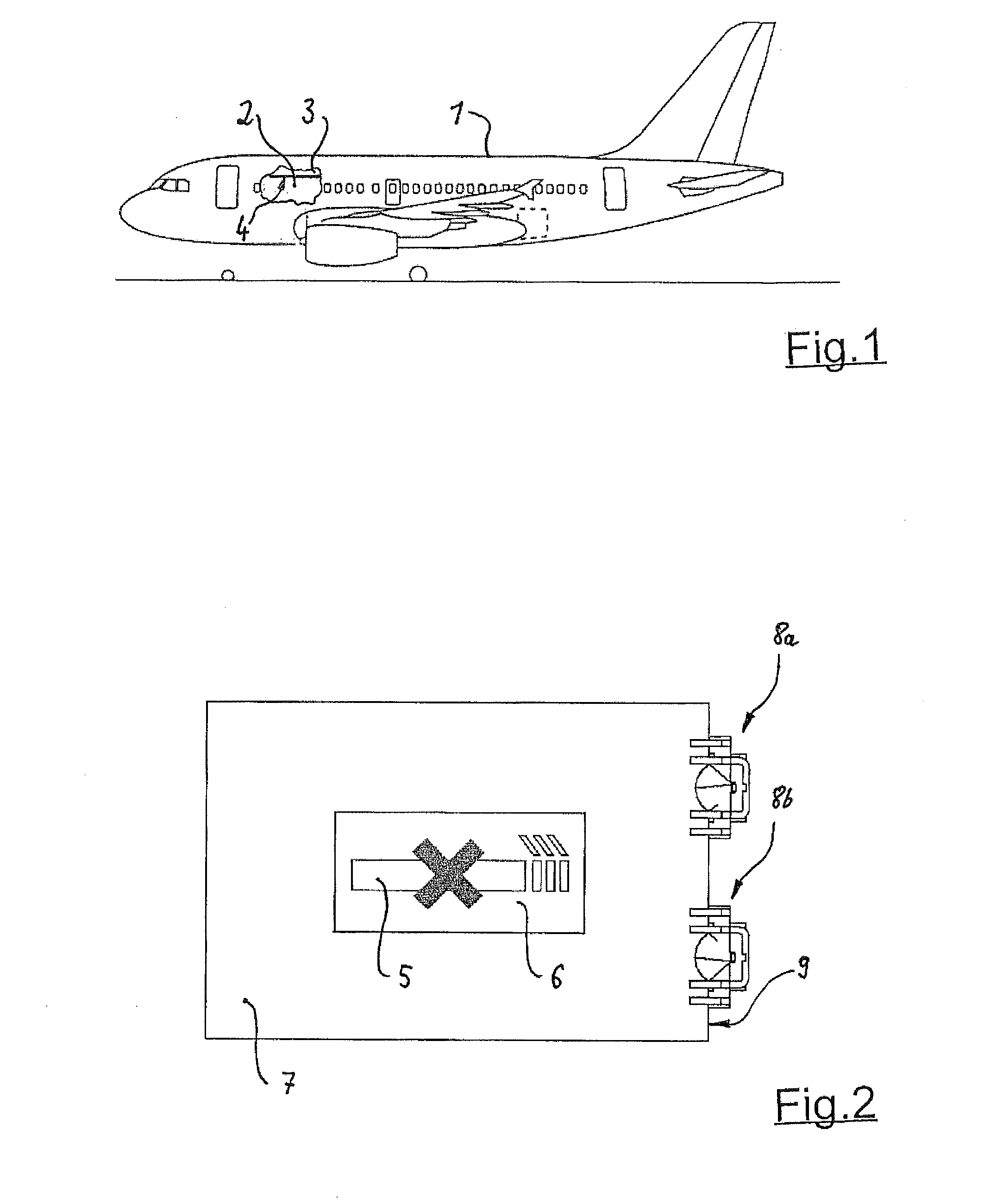
[0023]According to FIG. 1, the commercial aircraft comprises a passenger cabin (2) integrated into a fuselage (1), in which cabin equipment (3) is integrated in the form of overhead storage units arranged above the seat rows, the lower visible surface area of which is equipped with an illuminating display device in the form of a warning sign. Said warning sign may, if required, particularly during the starting and landing processes, be illuminated from the rear such that a coloured image lights up thus illuminating the warning.

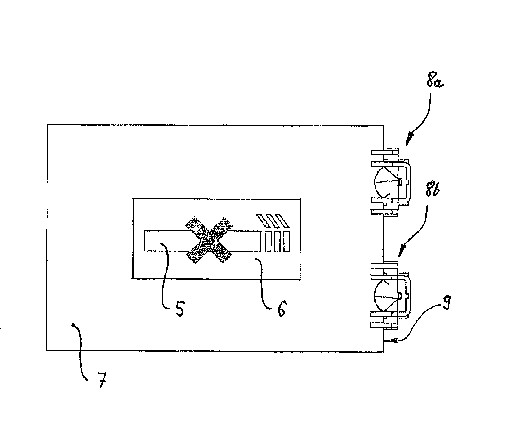
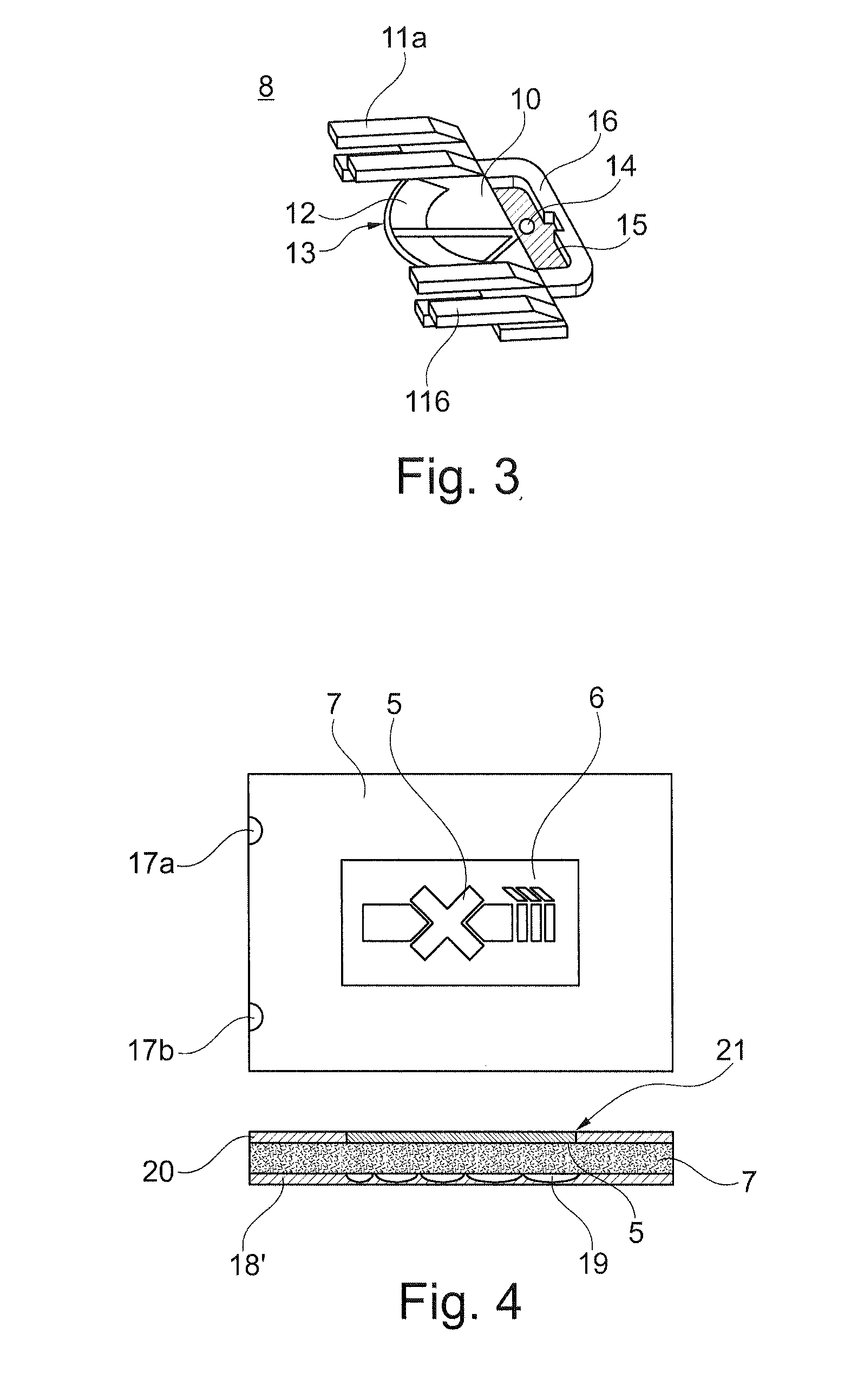
[0024]According to FIG. 2, said image (5) is embodied as a non-smoking sign in the present example of embodiment. The image (5) is located on a display area (6) of a synthetic film (7). On the side of the synthetic film (7) two light coupling units (8a, 8b) are arranged disposed spaced apart from one another. Through the adjacent edge area (9) light emitted from said light coupling unit (8a, 8b) is fed into the translucent film (7) that is forming a light duct...


PUM


Abstract

Flat illuminating display device with light emitting means to illuminate a film for display of an image applied to a display area, wherein the light emitting means are embodied as at least one light coupling unit arranged laterally at a translucent film thus forming a light duct, wherein the light such fed into the adjacent edge area into the film is reflected by a reflective layer, which is applied on at least one side, to homogeneously spread within the film, wherein a reflection screen to obtain a light emission is provided opposite of the display area to create said display area.

Description

CROSS-REFERENCE TO RELATED APPLICATIONS[0001]The present application is a continuation of International Application No. PCT / EP2011 / 051447, filed Feb. 2, 2011, published in German, which claims priority from German Application No. 10 2010 006 915.9 filed Feb. 4, 2010, and which claims the benefit of the filing date of U.S. Provisional Patent Application No. 61 / 301,378 filed on Feb. 4, 2010, the disclosures of which are hereby incorporated herein by reference.AREA OF THE INVENTION[0002]The invention relates to a flat illuminating display device comprising light-emitting means for illumination of a film to display an image applied to a display area. Further, the invention also relates to a particularly embodied light-emitting means within the framework of said illuminating display device. In addition, the invention relates to a commercial aircraft which is equipped with said flat illuminating display device in the area of the passenger cabin.[0003]The area of application of the illumin...

Claims


Application Information

Patent Timeline
Patent Type & Authority Applications(United States)
IPC IPC(8): B64D47/02F21V13/02
CPCB64D11/0015B64D2045/007G02B6/0043G02B6/006G09F2013/222G09F13/16G09F13/18G09F21/045G09F21/10G02B6/0091G09F21/049
Inventor METZECH, SABINEHESSE, KARSTENLIBRIZZI, ANGELOGUNTHER, JORG
Owner AIRBUS OPERATIONS GMBH
Why Eureka
Try Eureka