
Optical receiver/transmitter with circuit for determining modulation amplitude

a technology of optical receiver and modulation amplitude, applied in the direction of electrical equipment, transmission monitoring, electromagnetic transmission, etc., can solve the problems of corresponding relative deviation, too slow peak detector to provide accurate measurement of amplitude independent of signal content, etc., to reduce the peak detector bandwidth, increase the uncertainty of the magnitude of the received signal, and improve data transmission efficiency

Active Publication Date: 2013-01-17
NVIDIA DENMARK APS
View PDF1 Cites 21 Cited by
  • Summary
  • Abstract
  • Description
  • Claims
  • Application Information

AI Technical Summary

Benefits of technology

This patent describes a method and system for detecting peaks in a high-speed binary signal. The system uses a reference stage that is modulated by a binary signal or a copy of the signal. The method can tolerate delay between copies of the signal and accurately detect peak measures through averaging. This technique can be used in integrated circuits operating at high data rates, such as greater than 5 Gbit / s. The technical effect of this patent is to provide a reliable and accurate method for peak detection in high-speed binary signals.

Problems solved by technology

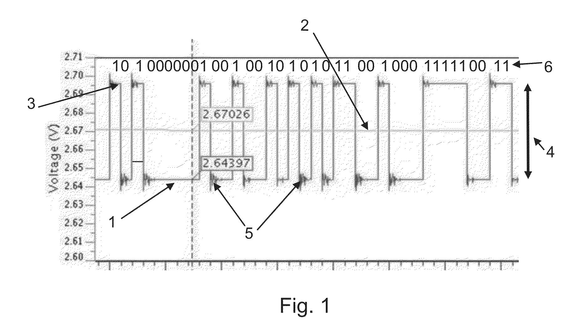
As an example consider that substantially identical peak detectors are applied to provide the first-peak-measure and the reference-peak-measure and these peak detectors are too slow to provide an accurate measure of the amplitude independent of signal content.
However, due to the identity of the signal content between the first- and reference binary signals the peak detectors will likely have corresponding relative deviations from the correct measurement at least when issues such as noise are ignored.

Method used


Image

  • Optical receiver/transmitter with circuit for determining modulation amplitude
  • Optical receiver/transmitter with circuit for determining modulation amplitude
  • Optical receiver/transmitter with circuit for determining modulation amplitude

Examples


Embodiment Construction

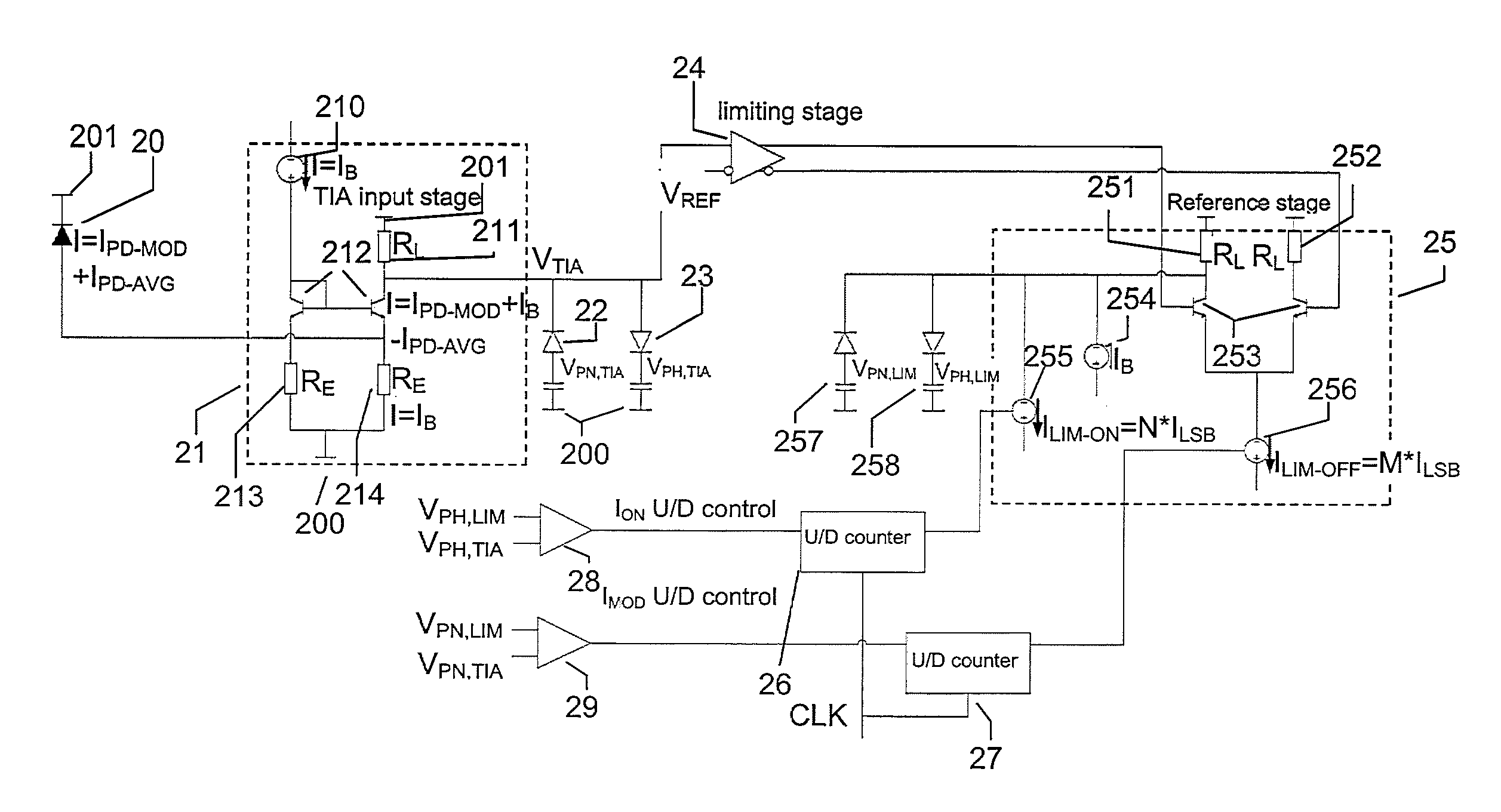
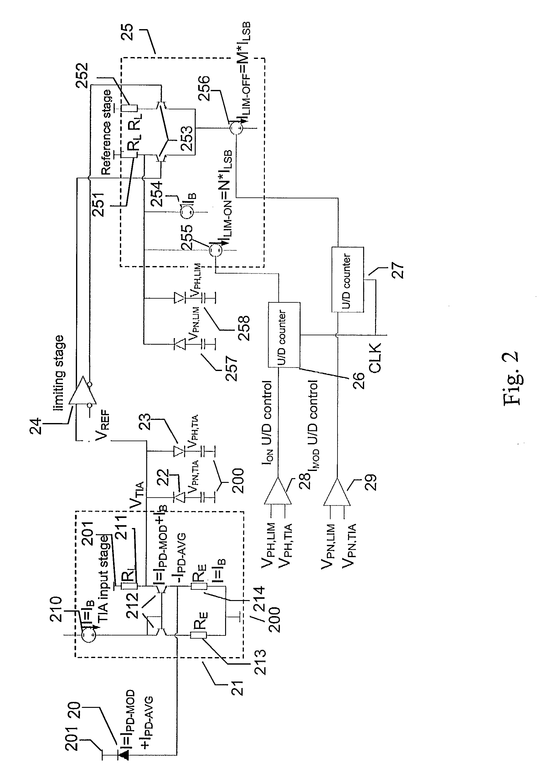
[0024]In one embodiment of the method of the invention the method comprises modulating said reference stage with said first binary signal or substantially a copy thereof. In this way the reference stage is modulated by the same signal content as the first binary signal. In most embodiments a delay between two copies of a signal can be tolerated without substantially affecting the accuracy of the determination of signal property because averaging is involved in providing the peak measures.

[0025]As mentioned above, one or more peak measures are obtained from the first-binary signal and the reference-binary-signal indicating that these values are measurements obtained via peak detection. However, in some embodiments it may be possible to apply other types of circuits suitable for detecting the amplitude of the signal. The peak detector may be arranged to detect the extreme of the signal waveform which would allow the detectors to e.g. detect peaks caused by transients in the signal. Ho...


PUM


Abstract

A method for an optical transmitter, receiver or transceiver allowing determination of a signal property of a first binary signal such as the modulation amplitude. The method applies a reference stage which is modulated by the signal content of the first binary signal to allow the determination.

Description

TECHNICAL FIELD[0001]The invention relates to a method and circuit for an optical receiver, transmitter or transceiver.BACKGROUND ART[0002]The demands for ever-increasing bandwidths in digital data communication equipment at reduced power consumption values are constantly growing. These demands not only require more efficient integrated-circuit components, but also higher performances, interconnect structures and devices. Indeed, as one example, the International Technology Roadmap for Semiconductors (ITRS) projects that high performance chips in the very near future will have operating frequencies, both on-chip and off-chip, rising above 50 GHz. Conventional metal-wire based interconnects have played a central role in the microelectronics revolution. It is apparent that wire-based interconnect devices will be challenged to enabling even higher operating frequencies.[0003]However, besides challenges with regard to bandwidth, the wire-based interconnect of the future may struggle sig...

Claims


Application Information

Patent Timeline
IPC IPC(8): H04B10/08
CPCH04B10/0779H04B10/0731
Inventor CHRISTENSEN, STEEN BAK
Owner NVIDIA DENMARK APS
Learn More