
Power supply and acquisition apparatus for on-line electric vehicle

Inactive Publication Date: 2013-01-24
KOREA ADVANCED INST OF SCI & TECH
View PDF1 Cites 4 Cited by
  • Summary
  • Abstract
  • Description
  • Claims
  • Application Information

AI Technical Summary

Benefits of technology

The present invention provides a power supply and acquisition apparatus for vehicles that allows for increased air gap between the power acquisition device and the surface of a road without increasing the width of the device. Additionally, the apparatus allows for a large steering deviation and reduces the EMF generated in a lateral of the road.

Problems solved by technology

Existing battery-powered electric vehicles have problems such as an excessive capacity, a long charging time, low charging efficiency and a short lifetime of batteries, a request for a charging station, and an increase in weight or volume and cost of the vehicles due to such batteries.
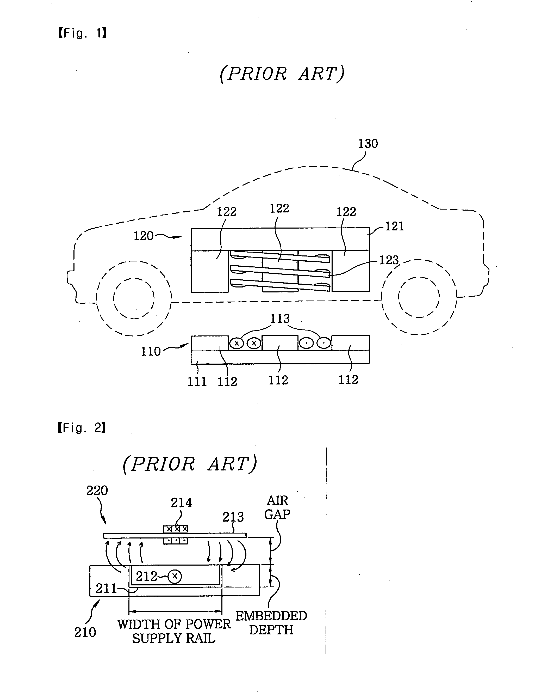
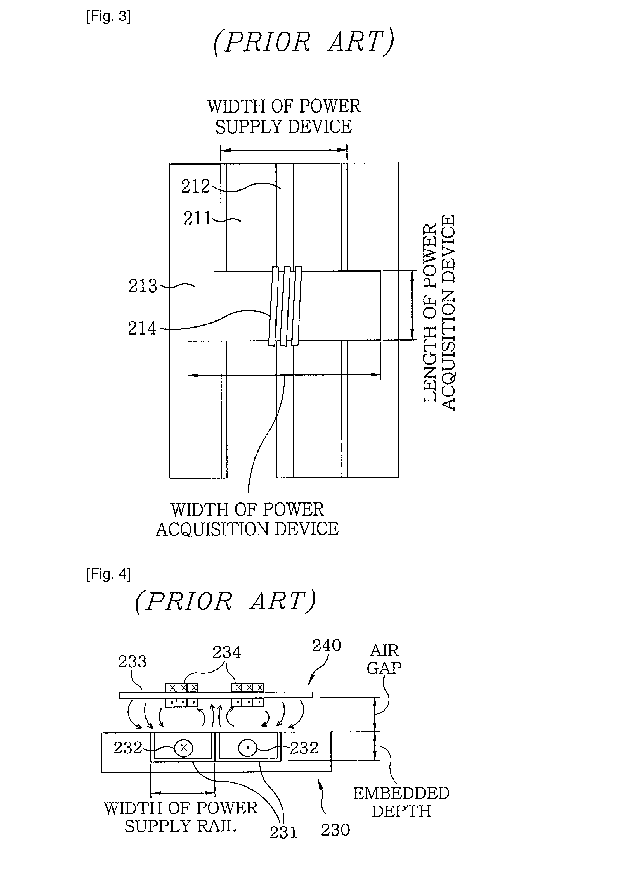
However, in the power supply and acquisition apparatus, there exists a problem in that the width of a power supply rail should be about two times larger than a desired air gap.
As such, if the width of the power supply device is excessively increased, the material cost of the core unit and a road building cost may increase.
Further, the intensity of the electromagnetic field (EMF) in a lateral of the vehicle may also increase, and thus, it is not easy to satisfy a permissible reference value (62.5 mG or less in a band of 20 kHz).
The width amounts to the overall width of a typical bus, and a passenger car does not satisfy such a condition.

Method used


Image

  • Power supply and acquisition apparatus for on-line electric vehicle
  • Power supply and acquisition apparatus for on-line electric vehicle
  • Power supply and acquisition apparatus for on-line electric vehicle

Examples


Embodiment Construction

[0050]Hereinafter, embodiments of the present invention will be described in detail with reference to the accompanying drawings so that they can be readily implemented by those skilled in the art. In the accompanying figures, like reference numerals refer to identical or functionally similar elements throughout the separate views.

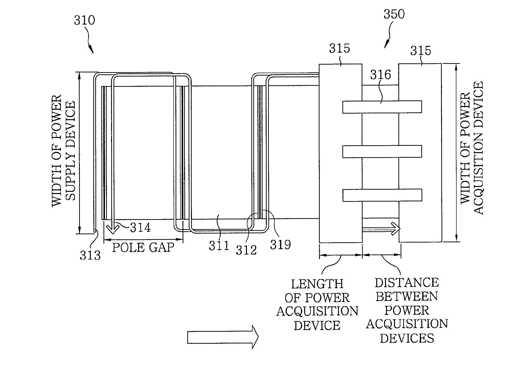
[0051]FIGS. 6 and 7 respectively illustrate a plan view and a side view of a dual-rail power supply and acquisition apparatus in accordance with an embodiment of the present invention. The dual-rail power supply and acquisition apparatus includes a Z-shaped power supply device 310 embedded in a road 320 and a power acquisition device 350 installed on the on-line electric vehicle. The Z-shaped power supply device 310 includes a plurality of power supply core units 311 embedded along the road 320 and two power supply lines 313 and 314.

[0052]Each power supply core unit 311 has a U-shape which is constructed by bending upward both end portions of a flat power s...


PUM


Abstract

A power supply and acquisition apparatus for an electrical vehicle includes a power supply device embedded along a road and a power acquisition device attached on the vehicle. The power supply device includes a plurality of power supply core units, each core unit having two opposite magnetic poles and formed in a direction perpendicular to a longitudinal direction of the road; and one or more power supply lines disposed along the longitudinal direction such that adjacent two magnetic poles have different polarities. The power acquisition device includes power acquisition core units; a connection member for connecting the power acquisition core units such that the power acquisition core units are spaced from each other by a distance between the magnetic poles; and a power acquisition coil wound around the respective power acquisition core units or the connection member.

Description

TECHNICAL FIELD[0001]The present invention relates to a non-contact power supply and acquisition apparatus for an on-line electric vehicle, and more particularly, to a power supply and acquisition apparatus for such an on-line electric vehicle, which allows a large air gap between a power acquisition device and a power supply device and allows a sufficient permissible range of a steering deviation.BACKGROUND ART[0002]Existing battery-powered electric vehicles have problems such as an excessive capacity, a long charging time, low charging efficiency and a short lifetime of batteries, a request for a charging station, and an increase in weight or volume and cost of the vehicles due to such batteries.[0003]In order to solve the above problems, there has been proposed a non-contact power delivery scheme using magnetic induction. In particular, one example of the non-contact power delivery scheme includes a power supply and acquisition apparatus for an on-line electric vehicle, which has...

Claims


Application Information

Patent Timeline
IPC IPC(8): B60L9/00H02J17/00
CPCB60L5/005B60L5/42B60L11/182B60M1/36B60L2200/26Y02T90/122Y02T90/14B60M7/003Y02T10/7005B60L2270/147H01F38/14Y02T90/12Y02T10/7072B60L53/12B60L53/39Y02T10/70H01F27/366H02J50/10H02J50/40B60Y2200/91
Inventor SUH, NAM PYOCHANG, SOON HEUNGCHO, DONG HOCHO, GYU HYEONGRIM, CHUN TAEKCHO, JUNG GOOKIM, JOUNG HO
Owner KOREA ADVANCED INST OF SCI & TECH
Learn More